Adjustable cutting guide

a cutting guide and adjustment technology, applied in metal working equipment, manufacturing tools, vices, etc., can solve problems such as problems, erroneous cutting and waste of materials, and methods that cannot be used, and achieve the effects of quick installation and removal of equipment, simple, easy and quick repetition

Inactive Publication Date: 2013-11-12
JAROCHE THOMAS
View PDF20 Cites 7 Cited by
  • Summary
  • Abstract
  • Description
  • Claims
  • Application Information

AI Technical Summary

Benefits of technology

[0010]In view of the foregoing references, the inventor recognized the aforementioned inherent problems and observed that there is a need for an adjustable cutting guide which allows a user to quickly install and remove the apparatus in a manner providing simple, easy, and quick repetition of common basic cutting tasks. Thus, the object of the present invention is to solve the aforementioned disadvantages and provide for this need.

Problems solved by technology

While this method does work, it is also plagued with problems.
First, the square can easily move before or during the cut, which results in an erroneous cut and wasted material.
Second, this method forces the user to place their hand near the blade of the saw, which is a significant safety concern.
Also, this method will not work at all when using other tools such as a router to produce dado cuts.
Many such devices are large and bulky, which can make them difficult to transport and difficult to manipulate between cuts.
Furthermore, many such devices provide an extensive range of adjustment mechanisms which results in increased time spent installing and removing the apparatus, even for simple tasks, making those apparatuses unsuited for simple, repetitious tasks.

Method used


Image

  • Adjustable cutting guide
  • Adjustable cutting guide
  • Adjustable cutting guide

Examples


Embodiment Construction

[0062]In accordance with the invention, the best mode is presented in terms of a preferred embodiment, herein depicted within FIGS. 1 through 5. However, the disclosure is not limited to a single described embodiment and a person skilled in the art will appreciate that many other embodiments are possible without deviating from the basic concept of the disclosure and that any such work around will also fall under its scope. It is envisioned that other styles and configurations can be easily incorporated into the teachings of the present disclosure, and only one particular configuration may be shown and described for purposes of clarity and disclosure and not by way of limitation of scope.

[0063]The terms “a” and “an” herein do not denote a limitation of quantity, but rather denote the presence of at least one of the referenced items.

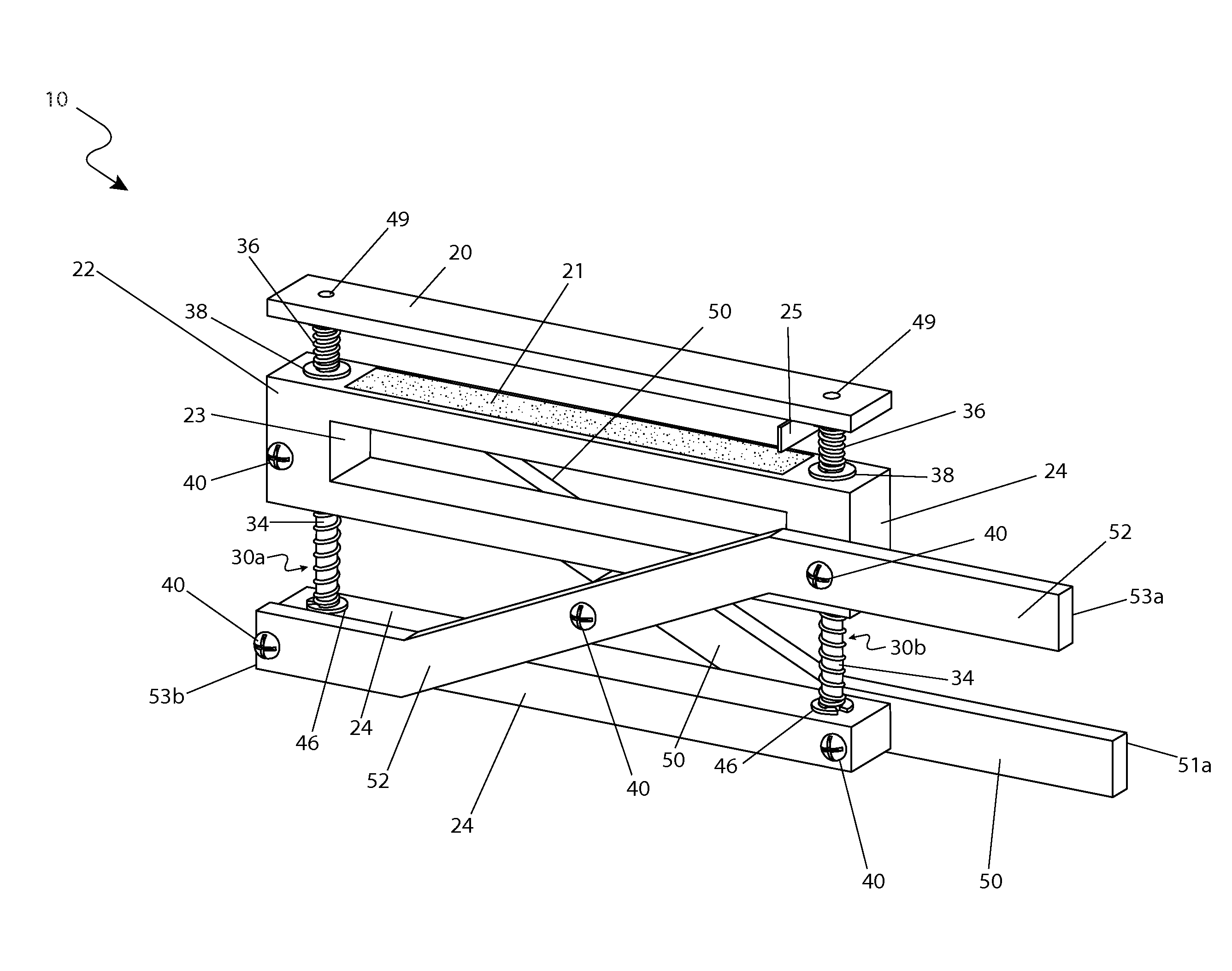
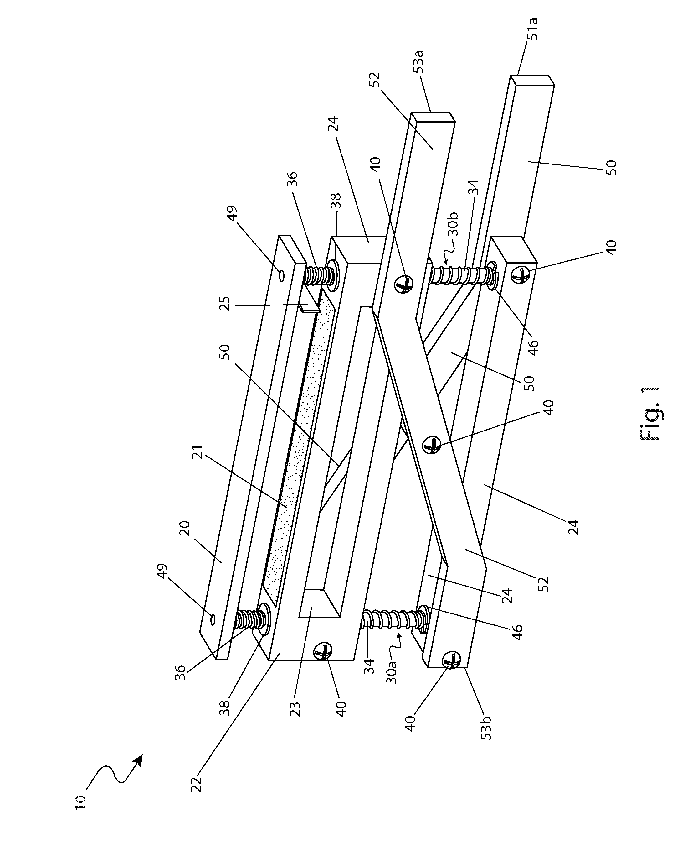
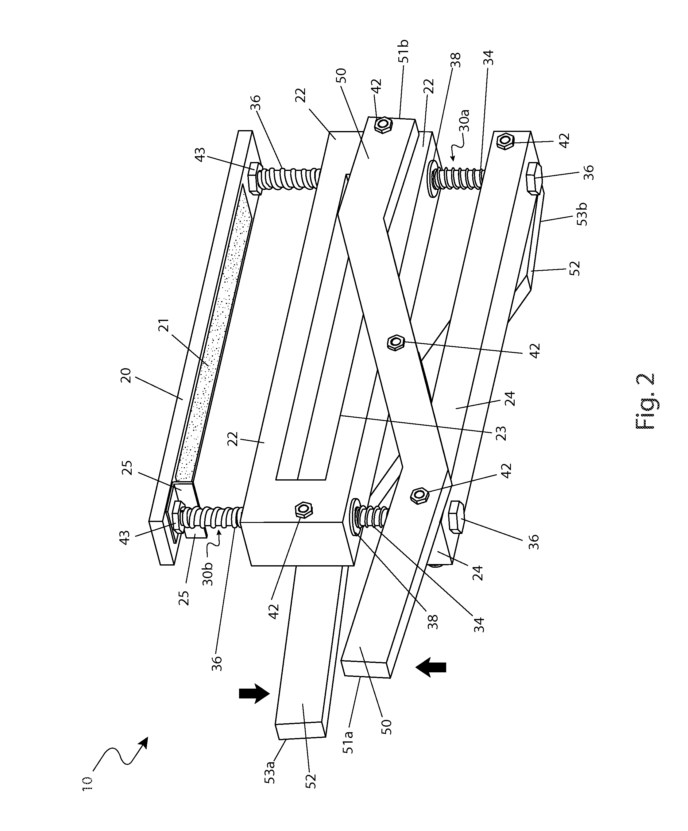
[0064]Referring now to FIGS. 1, 2, and 3, perspective and environmental views of the adjustable cutting guide (herein described as the “apparatus”) 10, ac...


PUM

PropertyMeasurementUnit
angleaaaaaaaaaa
angleaaaaaaaaaa
forceaaaaaaaaaa

Abstract

A clamping cutting guide to assist a carpenter in performing various wood techniques comprises a guide plate, a pair of guide rods, and a spring-loaded clamping portion. The guide rods extend perpendicularly downward along side areas and are inserted into respective springs to provide a clamping force to the stationary guide plate and a mobile clamping plate. The cutting guide also comprises a pair of pivoting handles open the clamp portions during loading/unloading of a desired object to be cut, thereby allowing a user to operate the guide using a single hand.

Description

RELATED APPLICATIONS[0001]There are no related applications currently co-pending with the present application.FIELD OF THE INVENTION[0002]The present invention relates generally to adjustable cutting guides, and in particular, to an adjustable cutting guide with an automatic spring-loaded clamping mechanism.BACKGROUND OF THE INVENTION[0003]As any professional contractor will attest, nothing beats having the proper tool for a job. The proper tool can save time and money, produce a higher quality job, reduce damage to equipment, and provide increased safety for workers. This is particularly true in fields is which require the use of a power saw to crosscut a piece of dimensional lumber such as a two-by-four.[0004]Many workers utilize a framing square to serve as a perpendicular guide when crosscutting lumber as described above. While this method does work, it is also plagued with problems. First, the square can easily move before or during the cut, which results in an erroneous cut an...

Claims


Application Information

Patent Timeline
Patent Type & Authority Patents(United States)
IPC IPC(8): B26D5/42B27B5/00B26D7/02B25B1/06
CPCB25B5/06Y10T83/5733Y10T83/7507
Inventor JAROCHE, THOMAS
Owner JAROCHE THOMAS
Why Eureka
Try Eureka