
Electric-leakage circuit breaker with reverse-wiring structure

A leakage circuit breaker and reverse wiring technology, applied in the direction of circuits, electric switches, electrical components, etc., can solve the problems of reduced service life, damage to leakage release coils, etc., and achieve the effect of ensuring normal use and avoiding damage

Active Publication Date: 2014-12-03
ZHEJIANG TENGEN ELECTRIC
View PDF8 Cites 8 Cited by
  • Summary
  • Abstract
  • Description
  • Claims
  • Application Information

AI Technical Summary

Problems solved by technology

[0003] In order to overcome the shortcomings and deficiencies of the background technology, the present invention provides a leakage circuit breaker with a reverse wiring structure, which solves the problem that the leakage release coil will be damaged when a leakage fault occurs in the existing leakage circuit breaker. , resulting in a reduction in service life

Method used


Image

  • Electric-leakage circuit breaker with reverse-wiring structure
  • Electric-leakage circuit breaker with reverse-wiring structure
  • Electric-leakage circuit breaker with reverse-wiring structure

Examples


Embodiment Construction

[0018] Embodiments of the present invention will be further described below with reference to the accompanying drawings:

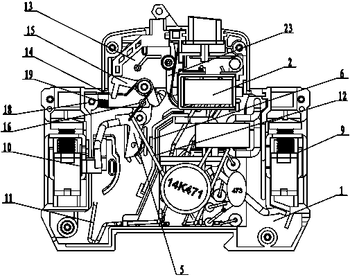
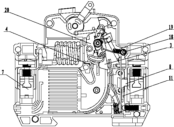
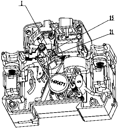
[0019] As shown in the figure, a leakage circuit breaker with a reverse wiring structure includes a housing 1, an operating mechanism, a contact mechanism, a leakage release 2, and terminals. The contact mechanism includes L-pole movable contacts 3, L The pole static contact 4, the N pole moving contact 5 and the N pole static contact 6, the L pole moving contact 3 and the N pole moving contact 5 are connected in linkage, and the connecting terminals include the L pole incoming terminal 7, The L pole outgoing line terminal 8, the N pole incoming line terminal 9 and the N pole outgoing line terminal 10 also include a live wire 11 and a neutral wire 12, and one end of the live wire 11 and the neutral wire 12 is connected to the leakage release 2 respectively, and the The other end of the live wire 11 is electrically connected to the L-pole outlet terminal 8...


PUM


Abstract

The invention relates to an electric-leakage circuit breaker with a reverse-wiring structure and mainly solves a problem, which exists in the prior electric-leakage circuit breakers, that under a reverse wiring condition, when an electric-leakage fault happens, a coil of an electric-leakage release is damaged so that reduction of service life is caused. The electric-leakage circuit breaker includes a casing, an operation mechanism, a contact mechanism, an electric-leakage release, connection terminals, a live line and a zero line. The contact mechanism includes L-pole moving and static contacts and N-pole moving and static contacts. The connection terminals include L-pole wire inlet and wire outlet terminals and N-pole wire inlet and wire outlet terminals. One end of the live line is connected with the electric-leakage release and one end of the zero line is connected with one end of the release through a circuit board control line. The other end of the live line is electrically connected with the L-pole wire outlet terminal and the other end of the zero line is electrically connected or disconnected with the N-pole moving contact through an on-off mechanism. The electric-leakage release moves and drives the on-off mechanism to control the zero line to be electrically disconnected with the N-pole moving contact. The contact mechanism switches on and drives the on-off mechanism to control the zero line to be electrically connected with the N-pole moving contact. Because the electric-leakage circuit breaker is provided with the on-off mechanism, even if a reverse wiring condition of a user happens, when an electric-leakage fault happens, the electric-leakage release moves and can cut off a power supplying voltage of the release through the on-off mechanism so that damage of the electric-leakage circuit breaker is prevented and normal use of the coil is ensured.

Description

technical field [0001] The invention relates to a circuit breaker, in particular to an earth leakage circuit breaker with a reverse wiring structure. Background technique [0002] The power supply voltage of the leakage release of the existing leakage circuit breaker is connected to the outlet terminal, one end of the live wire is connected to the leakage release, one end of the neutral line is connected to one end of the release through the circuit board control circuit, and the L pole and the The N-pole power supply voltage is to the leakage release. During use, the user may mistakenly connect the two poles of the grid to the outlet terminal. When a leakage fault occurs, the outlet terminal is always supplying power to the leakage release. Therefore, the leakage release will be damaged. The coil of the release will reduce the service life of the leakage release. Contents of the invention [0003] In order to overcome the shortcomings and deficiencies of the background t...

Claims


Application Information

Patent Timeline
Patent Type & Authority Applications(China)
IPC IPC(8): H01H71/10H01H9/24
Inventor 邹城华任昌宾董莎莎汪泰宇
Owner ZHEJIANG TENGEN ELECTRIC
Learn More