A Design Method for Space Layout of Multi-joint Pointing Mechanism of Deployable Spaceborne Antenna

A technology for pointing mechanism and layout design, which is applied in directions such as antennas, computing, and special data processing applications suitable for movable objects. Effect

Inactive Publication Date: 2016-07-06
DALIAN UNIV OF TECH
View PDF1 Cites 0 Cited by
  • Summary
  • Abstract
  • Description
  • Claims
  • Application Information

AI Technical Summary

Problems solved by technology

[0006] The spatial layout design of the multi-joint pointing mechanism of a large-scale deployable spaceborne antenna must satisfy both the pointing constraint and the position constraint of the focal length of the reflector. Neither of these two traditional design methods can satisfy these two constraints at the same time.

Method used


Image

  • A Design Method for Space Layout of Multi-joint Pointing Mechanism of Deployable Spaceborne Antenna
  • A Design Method for Space Layout of Multi-joint Pointing Mechanism of Deployable Spaceborne Antenna
  • A Design Method for Space Layout of Multi-joint Pointing Mechanism of Deployable Spaceborne Antenna

Examples


Embodiment Construction

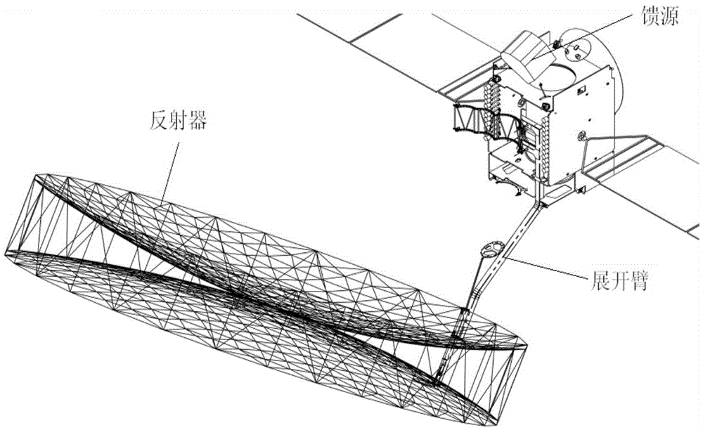
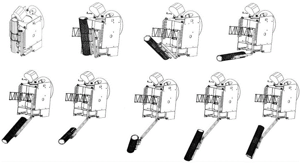
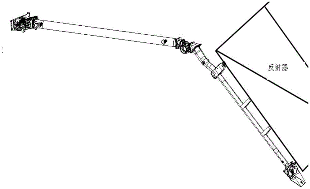
[0050] The present invention will be further described below in conjunction with the accompanying drawings. Such as figure 1 As shown, the feed point of a multi-joint pointing mechanism for a deployable spaceborne antenna is located on the satellite surface plane, the connection point between the root of the deployment arm and the satellite surface plane is the installation point of the pointing mechanism, and the connection point between the reflector and the end support arm and The vertical line of the line connecting the centers of the reflectors is the direction in which the antenna points. Such as figure 2 As shown in , the pointing mechanism has an initial installation orientation on the surface of the satellite. During the actual deployment process, the support arms should be folded with each other and in a folded state. Such as image 3 As shown, the antenna points in the same direction as the end support arm.

[0051] Such as Figure 7 As shown, a design method ...


PUM


Abstract

The invention discloses a design method for the space layout of a multi-joint pointing mechanism of an expandable space-borne antenna, which comprises the following steps: determining known conditions; setting constraint conditions; determining design goals; space layout design calculation; and obtaining design results. The present invention proposes a design goal and performs spatial layout calculation in combination with additional constraints that exist during the actual deployment of the antenna, and the design result can simultaneously satisfy the pointing constraints and position constraints in the spatial layout design of a multi-joint pointing mechanism for a large-scale expandable spaceborne antenna. The invention not only satisfies the antenna pointing constraint and the antenna focal length constraint in the pointing mechanism, but also adds additional constraint conditions in the process of folding and unfolding of the pointing mechanism, and considers the length limitation of each support arm, and proposes to make the support arm material The most economical design goal makes the spatial layout design result not only conform to the engineering reality, but also save material and processing costs.

Description

technical field [0001] The invention relates to the design and processing technology of a satellite and its accessories, in particular to a design method for the spatial layout of a multi-joint pointing mechanism of a large expandable satellite antenna. [0002] The feed point of the multi-joint pointing mechanism of the space-borne antenna is separated from its antenna reflection surface. The present invention proposes a design method for its spatial layout, which satisfies the requirements of the pointing mechanism for the antenna focal length while satisfying the antenna pointing to the feed source after the pointing mechanism is deployed. Background technique [0003] The multi-joint pointing mechanism of a large-scale expandable spaceborne antenna is composed of the antenna mainly including a reflector, a feed source assembly and an expansion arm. The function of the expansion arm is to support the spatial layout, also called the support arm. The component is separated ...

Claims


Application Information

Patent Timeline
Patent Type & Authority Patents(China)
IPC IPC(8): H01Q1/28G06F17/50
Inventor 周文雅张朔穆瑞楠杜剑明
Owner DALIAN UNIV OF TECH
Why Eureka
Try Eureka