Elevator anti-falling device

An anti-fall and elevator technology, applied in transportation, packaging, elevators, etc., can solve the problems of elevator falling, detection failure, threatening people's life and property safety, etc., to achieve reliable fault detection, improve safety, and reliable anti-fall performance.

Inactive Publication Date: 2014-12-10
张龙俊
View PDF8 Cites 15 Cited by
  • Summary
  • Abstract
  • Description
  • Claims
  • Application Information

AI Technical Summary

Problems solved by technology

However, when the elevator is running, the phenomenon of the elevator falling occasionally occurs, which seriously threatens the safety of people's lives and property, resulting in irreparable losses.
[0003] Some elevator anti-falling devices are disclosed in the prior art, including anti-falling components and control devices, but most of the control devices use photoelectric control devices. Although this kind of device has a high degree of detection, it also has a state of detection failure, which leads to the elevator falling. danger

Method used


Image

  • Elevator anti-falling device
  • Elevator anti-falling device
  • Elevator anti-falling device

Examples


Embodiment 1

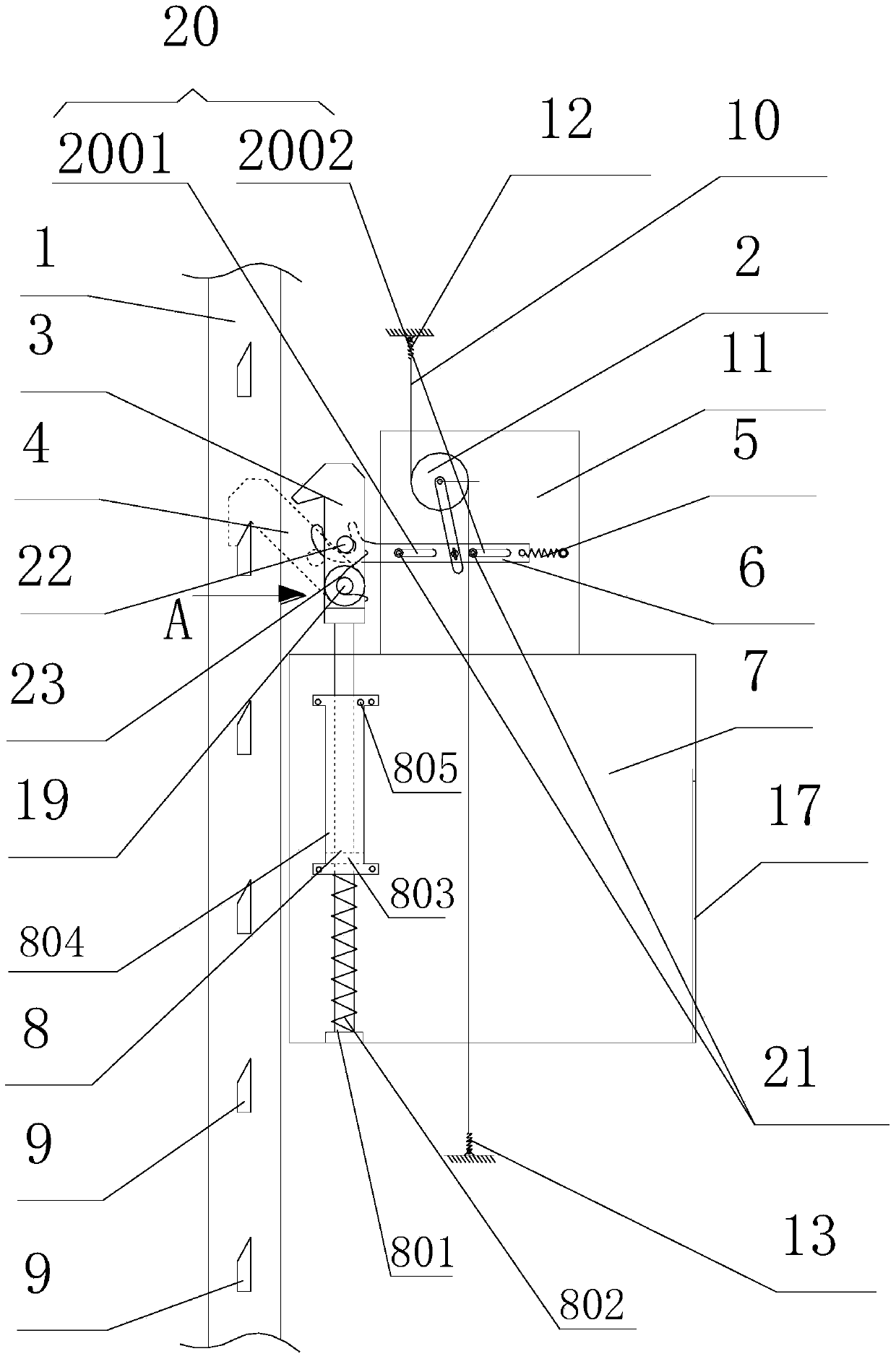
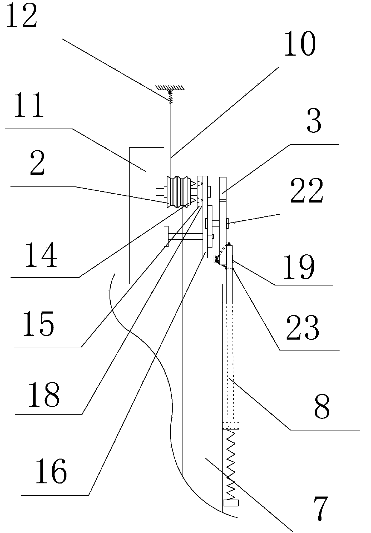
[0027] The elevator anti-fall device of the present embodiment includes an anti-fall component and a control device, such as figure 1 , figure 2 as shown,

[0028] The top of the elevator car 7 is equipped with a fixed seat 11, and the outer wall of the elevator car 7 is equipped with a braking device 8 with an air damper; control device;

[0029] Such as figure 1 As shown, the control device includes an actuator assembly 2, and the actuator assembly 2 is installed on a fixed seat 11; a traction wire rope 10 is wound on the actuator assembly 2, and the upper end of the traction wire rope 10 is connected with an upper buffer spring 12, and the upper buffer spring 12 is fixed on the top of the well above the car 7; the lower end of the traction wire rope 10 is connected to the lower buffer spring 13, and the lower buffer spring 13 is fixed on the bottom of the well below the car 7; the elevator moves up and down in the elevator shaft, and the actuator assembly 2 Move up and...

Embodiment 2

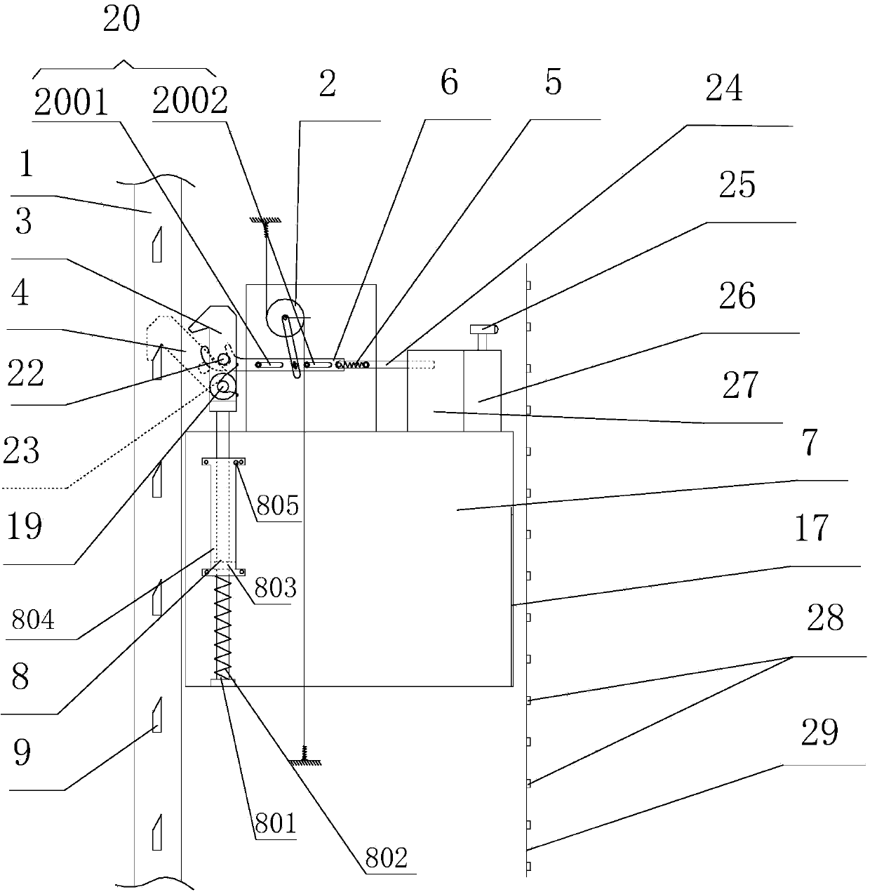
[0036] Such as image 3 As shown, the present embodiment adds a photoelectric control device on the basis of Embodiment 1. The photoelectric control device includes a push-out electromagnet 27, a photoelectric control instrument 26 installed on the top of the elevator car 7, and a photoelectric emission controller connected with the photoelectric control instrument. Receiving head 25 and the reflected signal board 28 that is arranged on the elevator guide rail two 29; Elevator guide rail one 1 and elevator guide rail two 29 are arranged symmetrically about car 7, and reflected signal board 28 is arranged symmetrically with photoelectric transmitting and receiving head 25 simultaneously; Iron 27 comprises push-out type electromagnet push rod 24, and push-out type electromagnet push rod 24 is connected with execution shift fork cross bar 6; Photoelectric transmitting and receiving head 25 transmits signal to reflection signal board 28, and receives the signal that reflection sign...


PUM


Abstract

The invention discloses an elevator anti-falling device. The elevator anti-falling device comprises an anti-falling part and a control device. The control device comprises an actuator assembly installed on an elevator car and a centrifugal jaw clutch installed on the actuator assembly, a driven gear of the centrifugal jaw clutch is connected with an execution connecting rod assembly, and the execution connecting rod assembly is connected with the anti-falling part. A steel wire rope is wound on the actuator assembly, and the two ends of the steel wire rope are connected with the top and the bottom of an elevator shaft. The mode of mechanical detection control devices is adopted in the elevator anti-falling device of the structure, the falling speed of an elevator is detected by using the rotation speed of the centrifugal jaw clutch installed on the car, braking of the anti-falling device is realized, the anti-falling device is accurate in detection speed and has a few detection faults, the working performance of the anti-falling device can be obviously improved and the safety of operation of the elevator is improved.

Description

technical field [0001] The invention relates to an anti-falling device, in particular to an elevator anti-falling device. Background technique [0002] With the continuous development of urban construction and the continuous increase of high-rise buildings, elevators are widely used in the national economy and life. As a means of transportation running vertically in high-rise buildings, elevators are inseparable from people's daily life. However, when the elevator is in operation, the phenomenon of elevator falling occurs occasionally, which seriously threatens the safety of people's lives and property, and causes irreparable losses. [0003] Some elevator anti-falling devices are disclosed in the prior art, including anti-falling components and control devices, but most of the control devices use photoelectric control devices. Although this kind of device has a high degree of detection, it also has a state of detection failure, which leads to the elevator falling. danger....

Claims


Application Information

Patent Timeline
Patent Type & Authority Applications(China)
IPC IPC(8): B66B5/04B66B5/26
Inventor 张龙俊张佳
Owner 张龙俊
Why Eureka
Try Eureka