Bridge foundation horizontal load test device and test method

A bridge foundation and test method technology, which is applied in the test of basic structure, basic structure engineering, construction, etc., can solve the problems of non-professional personnel who are difficult to understand, not intuitive enough, lack of image, etc.

Inactive Publication Date: 2015-12-09
SOUTHEAST UNIV
View PDF5 Cites 0 Cited by
  • Summary
  • Abstract
  • Description
  • Claims
  • Application Information

AI Technical Summary

Problems solved by technology

Moreover, the current domestic and foreign research focuses on macroscopic mechanics, and the research on the mesoscopic fundamental mechanism based on the interaction of soil, foundation and soil from the mesoscopic perspective is still lacking.
[0003] The traditional model test of the foundation generally measures the change of the displacement and force of the foundation, and conducts research by establishing the relationship between force and displacement. This macroscopic method requires good mathematical reasoning ability and three-dimensional space imagination ability, and this method is not intuitive enough. , it will be difficult for non-professionals to understand

Method used


Image

  • Bridge foundation horizontal load test device and test method
  • Bridge foundation horizontal load test device and test method
  • Bridge foundation horizontal load test device and test method

Examples


Embodiment 1

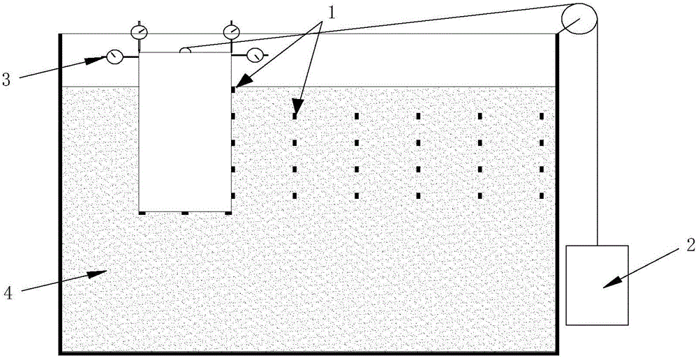
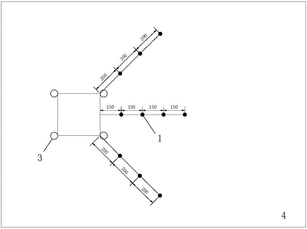
[0047] In this embodiment, the full-model test device is used to analyze and calculate the horizontal load of the bridge foundation. The test device is as follows: figure 1 and figure 2 As shown, it consists of a counterweight 2, an earth pressure cell 1, a test tank 4, and a dial indicator 3. The long-term load is applied to the model through the counterweight 2, and the earth pressure cell 1 is used to measure the change of soil pressure on the soil body and the model wall. The overturning, rotation and translation of the model are analyzed with the data of dial indicator 3.

[0048] When in use, the steps of the macroscopic observation test are as follows:

[0049] Step1: Set up the test components; set and calibrate all the components used in the test (displacement gauge, oil pressure gauge, earth pressure cell, etc.) to ensure correct use and reading.

[0050] :During the test, the colored sand used for the test was paved in layers, and the thickness of each layer w...

Embodiment 2

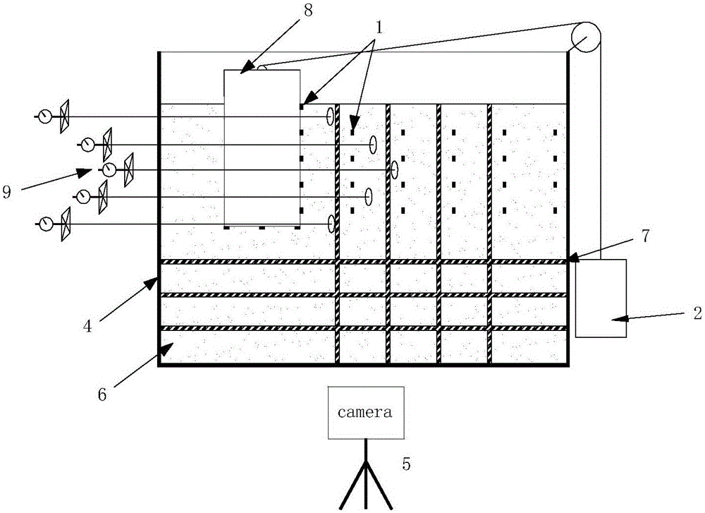
[0062] In this embodiment, the PIV camera semi-model test device is used to analyze and calculate the horizontal load of the bridge foundation, and the semi-model is mesoscopically photographed. According to the mesoscopic parameters such as particle displacement and rotation, local porosity, and particle coordination number, the Analyze the creep behavior of soil under long-term loading.

[0063] Such as image 3 As shown, one facade of test tank 4 is made of transparent plexiglass, and half model 8 separated along the symmetry axis of the whole model is taken. At the same time, monochromatic colored sand layers 7 for visual observation are arranged at the same intervals, the model 8 is loaded by the counterweight 2, and a digital camera 5 for PIV shooting is erected outside the box perpendicular to the central axis of the plexiglass. Simultaneously, a soil displacement measuring device 9 is embedded in the soil to measure the displacement of the deep soil. The embedding me...


PUM


Abstract

The invention discloses a bridge foundation lateral loading testing device and method. The testing device comprises a full-model device and a half-model device, wherein the full-model device is used for measuring macroscopic characteristics such as soil pressure, soil mass displacement and overturn, transmission and horizontal movement of a foundation model, and the half-model device is used for analyzing microscopic mechanisms such as displacement, rotation and local porosity of particles. The testing and analyzing method enables the macroscopic characteristics and microscopic mechanisms to be combined, and macroscopic phenomena such as a bearing mechanism and a failure mode of a foundation under the effect of loading are analyzed from the microscopic mechanics angle. The bridge foundation lateral loading testing device and method not only have theoretical derivation and verification, but also have visualizability of the particle scale angle, and enable people to be clear at a glance.

Description

technical field [0001] The invention relates to a bridge foundation horizontal load test device and a test method, belonging to the field of bridge foundation experiment research. Background technique [0002] The construction of cross-sea bridges at home and abroad is increasing day by day, and many new types of large-scale bridge foundation forms have emerged. Most of these basic forms lack a theoretical research basis, and field experiments are difficult to carry out. Therefore, the engineering community generally uses model tests for research. Moreover, the current research at home and abroad focuses on the macroscopic mechanics, and the research on the mesoscopic fundamental mechanism based on the interaction of soil, foundation and soil from the mesoscopic point of view is still lacking. [0003] The traditional model test of the foundation generally measures the change of the displacement and force of the foundation, and conducts research by establishing the relatio...

Claims


Application Information

Patent Timeline
Patent Type & Authority Patents(China)
IPC IPC(8): E02D33/00
Inventor 赵学亮朱智荣龚维明
Owner SOUTHEAST UNIV
Why Eureka
Try Eureka