Device and test method for detecting crack resistance of asphalt mixture
A technology of asphalt mixture and anti-cracking performance, which is applied in the direction of measuring device, using stable tension/pressure to test material strength, analyzing materials, etc. It can solve the problem of poor clamping stability and flexibility and inability to perform mechanical performance tests. Universal device, low utilization rate of equipment, etc., to achieve the effect of convenient test analysis, controllable loading force and loading pressure position, simple and reasonable clamping
- Summary
- Abstract
- Description
- Claims
- Application Information
AI Technical Summary
Problems solved by technology
Method used
Image
Examples
Embodiment 1
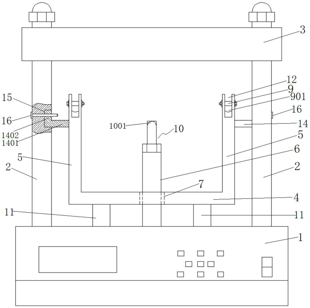
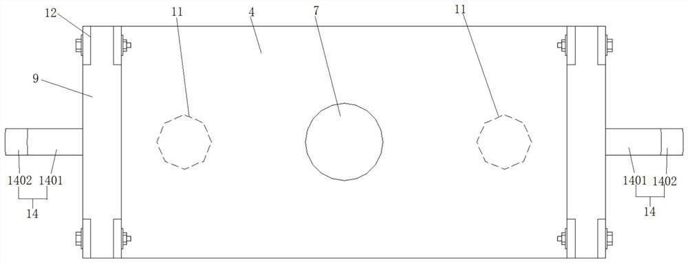
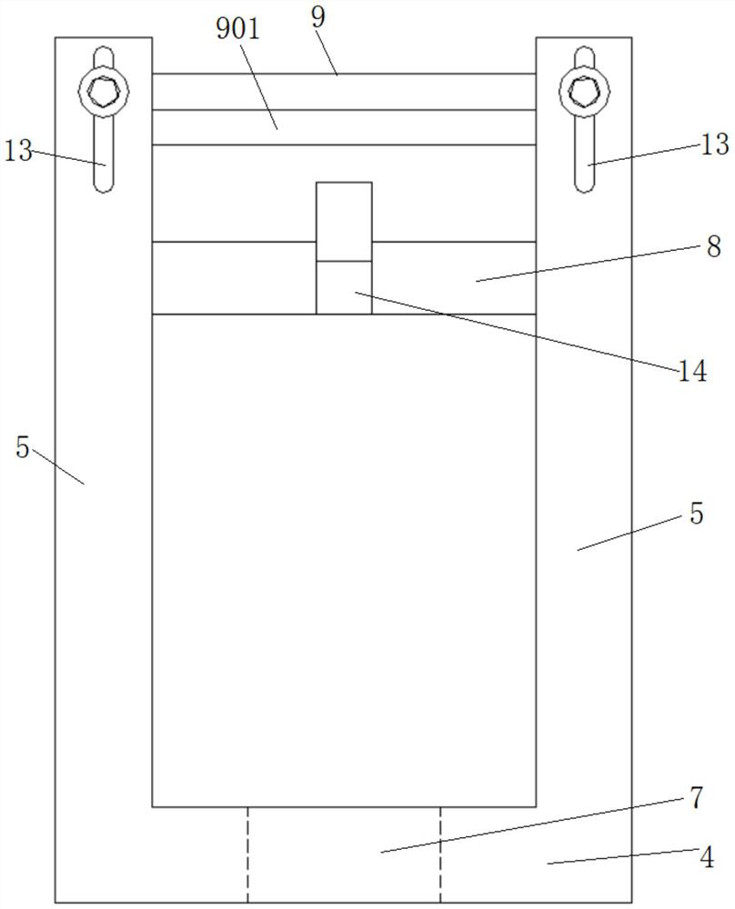
[0054] Such as Figure 1 ~ Figure 4 As shown, a device for testing the anti-crack performance of asphalt mixtures includes a body 1, a dowel 6 is provided in the middle of the body 1, and a detachably connected clamp assembly is provided above the body 1. The clamp assembly comprises a clamp base plate 4, and the four corners of the clamp base plate 4 are respectively provided with vertical support rods 5, and a pair of (a pair on the left side or a pair on the right side) in the width direction is arranged between the support rods 5. Horizontal supporting plates 8 are respectively provided, and side pressing plates 9 are arranged above the supporting plates 8, and the two ends of the side pressing plates 9 are detachably and slidingly connected with the supporting rods 5 respectively; The middle part is provided with a through hole 7, the diameter of the through hole 7 is larger than the diameter of the dowel bar 6 and coaxially arranged with the dowel bar 6; the end of the d...
Embodiment 2
[0070] This embodiment provides a side support structure of the clamp assembly in the first embodiment.
[0071] Such as Figure 1 ~ Figure 3 As shown, the two sides of the clamp assembly are respectively provided with side support rods 14, and the side support rods 14 have an integral horizontal connecting rod 1401 and a vertical connecting rod 1402, and the ends of the horizontal connecting rod 1401 are screwed on On the support plate 8 of the clamp assembly; the inner side of the column 2 is respectively provided with a connecting groove 15 adapted to the vertical connecting rod 1402, and the vertical connecting rod 1404 moves into the connecting groove 15 It is connected with the column 2 through the positioning pin 16.
[0072] The upper surface of the horizontal connecting rod 1401 is slightly lower than the upper surface of the support plate 8 .
[0073] The setting of the side support bar 14 can further improve the installation stability of the clamp assembly, which ...
Embodiment 3
[0076] The difference between this embodiment and the first embodiment is that another structure of the support legs and the circular slideway is provided.
[0077] Such as Figure 8 with Figure 9 As shown, the section of the circular slideway 101 is an inverted "T" shape, the flange side 1101 is arranged at the end of the support foot 11, and the flange side 1101 and the lower end of the support foot 11 are both located at the end of the support foot 11. In the circular slide 101 , the flange 1101 is provided with fixing pin holes 19 , and the centerline of the circular slide 101 is provided with corresponding fixing pin holes.
[0078] Since the flange 1101 is arranged at the end of the leg 11 and is located in the inverted "T"-shaped circular slideway 101, it will not move up and down by itself. The vertical limit can be realized, and the operation is simpler and more convenient.
[0079] Furthermore, the circular slideway 101 is also provided with a pair of relief groo...
PUM
 Abstract
Description
Claims
Application Information
 - R&D
- Intellectual Property
- Life Sciences
- Materials
- Tech Scout
- Unparalleled Data Quality
- Higher Quality Content
- 60% Fewer Hallucinations
Browse by: Latest US Patents, China's latest patents, Technical Efficacy Thesaurus, Application Domain, Technology Topic, Popular Technical Reports.
© 2025 PatSnap. All rights reserved.Legal|Privacy policy|Modern Slavery Act Transparency Statement|Sitemap|About US| Contact US: help@patsnap.com


