Wireless lock

A wireless and wireless communication module technology, applied in the field of wireless locks, can solve the problems of complex structure, high design cost and large volume of locks, and achieve the effects of high security, simple structure and saving design cost.

Active Publication Date: 2014-12-10
NANJING IOT SENSOR TECH
View PDF7 Cites 4 Cited by
  • Summary
  • Abstract
  • Description
  • Claims
  • Application Information

AI Technical Summary

Problems solved by technology

[0005] The purpose of the present invention is to provide a wireless lock to solv...

Method used


Image

  • Wireless lock
  • Wireless lock
  • Wireless lock

Examples


Embodiment Construction

[0020] In order to facilitate the understanding of those skilled in the art, the present invention will be further described below in conjunction with the embodiments and accompanying drawings, and the contents mentioned in the embodiments are not intended to limit the present invention.

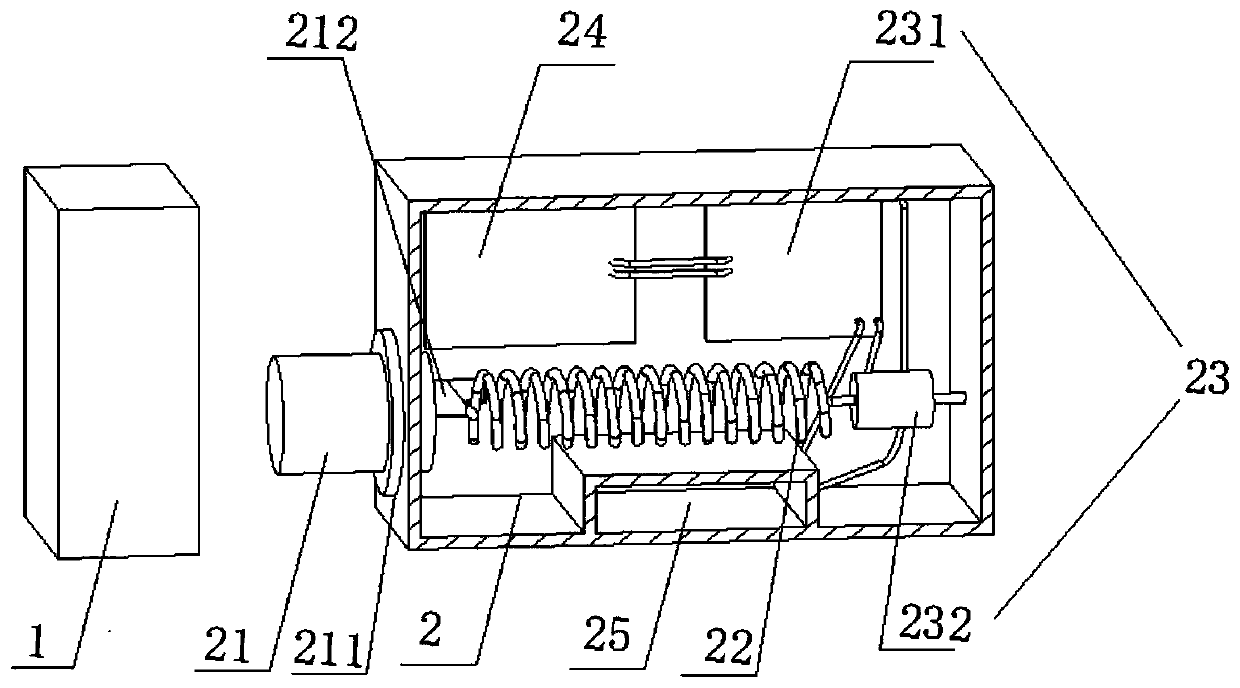
[0021] refer to Figure 1 to Figure 3 As shown, the wireless lock of the present invention is composed of a lock head 1 and a lock body 2 cooperating with the lock head 1. The lock body 2 is provided with a lock bolt 21, a temperature-controlled deformation spring 22 fixedly connected with the lock bolt 21, and a The temperature control deformation spring 22 is fixedly connected to the heater 23 and the control unit 24 connected to the heater 23, wherein:

[0022] The lock bolt 21 is axially slidable and telescopically arranged in the lock body 2, and the two can cooperate by means of a bearing 211, which can also reduce sliding resistance; a handle 212 can also be welded on the circumferent...


PUM


Abstract

The invention discloses a wireless lock. The wireless lock is composed of a lock head and a lock body matched with the lock head. The lock body is internally provided with a lock bolt, a temperature control deformation spring fixedly connected with the lock bolt, a heater fixedly connected with the temperature control deformation spring, and a controlling unit connected with the heater. The wireless lock is controlled according to the temperature in a wireless mode, the structure is simple, the design cost is saved, no key is used, and automation and accuracy are achieved.

Description

technical field [0001] The invention relates to the technical field of locks, in particular to a wirelessly controlled lock that realizes locking / unlocking by changing the temperature of a deformed spring. Background technique [0002] At present, there are various locks on the market, but these locks are all designed with high-strength anti-theft performance in mind, so the design is more complicated, there are many mechanical structural components, and the cost is high. With the advancement of technology, various smart locks are also Emerging in the market, the locks are unlocked through door cards, passwords or mobile phones, and these smart locks use micro-motors to drive the lock bolts to move when unlocking, which leads to complex design mechanisms of locks, large volume, and high production costs. high, wasting energy. [0003] Memory metal, its crystal structure changes with temperature in solid state, for example: the crystal structure of nickel-titanium alloy is d...

Claims


Application Information

Patent Timeline
IPC IPC(8): E05B51/00E05B15/10E05B17/22
Inventor 朱俊岗朱峰朱俊岭余建美
Owner NANJING IOT SENSOR TECH
Why Eureka
Try Eureka