
Tunnel boring machine torque load simulation hydraulic system

A tunnel boring machine and torque load technology, which is applied in the direction of mechanical equipment, mechanical component testing, fluid pressure actuation devices, etc., can solve the problems of restricting the accuracy of construction data collection, difficult data collection, and inability to simulate dynamic torque loads

Active Publication Date: 2014-12-10
ZHEJIANG UNIV
View PDF4 Cites 1 Cited by
  • Summary
  • Abstract
  • Description
  • Claims
  • Application Information

AI Technical Summary

Problems solved by technology

[0004] The tunnel construction environment restricts the accuracy of construction data collection, and the existing theoretical calculations cannot take into account the complex construction environment. Therefore, physical simulation tests are the main feasible solution
Some existing torque load simulation schemes use buried soil boxes or prevent rock blocks as load simulations. Although they have the advantage of being more accurate, it is not easy to replace buried soil and rock blocks, data acquisition is difficult, and the replacement cost is high; the hydraulic system has power density. Large, and has a mature rotary load element hydraulic pump and supporting sensors, so the use of hydraulic systems for torque load simulation has advantages that other solutions cannot replace
[0005] Existing hydraulic torque load simulation systems, such as patent CN201110395900.7, only use a proportional relief valve as load simulation, which can only simulate geostatic loads, and cannot simulate dynamic torque loads related to cutter head speed during excavation
Therefore, there is currently no hydraulic system suitable for tunnel boring machine torque load simulation

Method used


Image

  • Tunnel boring machine torque load simulation hydraulic system

Examples


Embodiment Construction

[0014] The present invention will be further described below in conjunction with the accompanying drawings and embodiments.

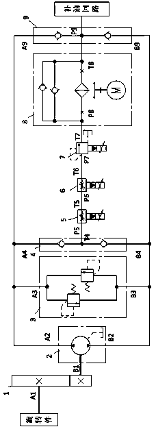
[0015] Such as figure 1 As shown, the present invention includes a rotating member, a speed increaser 1, a load simulation pump 2, a closed circuit safety valve group 3, an oil outlet check valve group 4, a slender hole electromagnetic proportional throttle valve 5, a thin edge electromagnetic proportional section Flow valve 6, electromagnetic proportional overflow valve 7, oil air cooling valve group 8, oil replenishment check valve group 9 and oil replenishment circuit; the rotating part is connected to the low-speed input end A1 of the speed increaser 1, and the high-speed speed increaser 1 The output terminal B1 drives the load simulation pump 2, a closed circuit composed of an oil port A2 of the bidirectional load simulation pump 2 and two relief valves installed in reverse parallel, an oil port A3 of the safety valve group 3, and two check valves ...


PUM


Abstract

The invention discloses a tunnel boring machine torque load simulation hydraulic system. The tunnel boring machine torque load simulation hydraulic system comprises a rotating part, a speed increaser, a load simulation pump, a closed loop safety valve set, an oil outlet check valve set, a long and thin hole magnetic proportional throttle valve, a thin-cutting-edge magnetic proportional throttle valve, a magnetic proportional overflow valve, an oil air-cooling valve set, an oil supplementing check valve set and an oil supplementing loop. The magnetic proportional throttle valve and the magnetic proportional overflow valve different in opening type are connected in series, parameter adjustment is performed in a unified mode, and torque load setting, rock-soil static pressure setting and cutter disc rotation speed are considered in a unified mode, so that high-fidelity simulation of torque load of a tunnel boring machine is achieved. The load valve set scheme is suitable for dynamic simulation of other types of loads as well.

Description

technical field [0001] The invention relates to a load simulation hydraulic system, in particular to a tunnel boring machine torque load simulation hydraulic system. Background technique [0002] Tunnel boring machine is a kind of motor or hydraulic motor to drive the cutter head to rotate. Under the action of the hydraulic propulsion system, the cutter head is pushed towards the rock and soil layer, and the cutter on the cutter head destroys the rock and soil layer, so that the entire section of the tunnel can be excavated at one time. Formed large construction machinery. The tunnel boring machine construction method integrates tunnel excavation, muck removal, ventilation and dust removal, tunnel track laying, and wind, hydropower extension, and has the characteristics of fast, high-quality, safe, and environmentally friendly construction. [0003] The tunnel boring machine has a huge structure, complex system, high cost, and poor adaptability to different geological condi...

Claims


Application Information

Patent Timeline
Patent Type & Authority Applications(China)
IPC IPC(8): F15B11/00G01M13/00
Inventor 龚国芳刘统张振饶云意王伟吴伟强杨华勇
Owner ZHEJIANG UNIV
Learn More