
Thrust-load-simulation hydraulic system of tunnel boring machine

A technology of tunnel boring machine and thrust load, which is applied to mechanical equipment, fluid pressure actuating devices, servo motors, etc., can solve the problems of inability to simulate the dynamic load of tunneling, restricting the accuracy of construction data collection, and difficult to replace buried soil rock blocks.

Inactive Publication Date: 2015-03-11
ZHEJIANG UNIV
View PDF6 Cites 5 Cited by
  • Summary
  • Abstract
  • Description
  • Claims
  • Application Information

AI Technical Summary

Problems solved by technology

[0004] The tunnel construction environment restricts the accuracy of construction data collection, and the existing theoretical calculations cannot take into account the complex construction environment. Therefore, physical simulation tests are the main feasible solution
Some of the existing thrust load simulation schemes use buried soil boxes or placed rock blocks as load simulation. Although it has the advantage of being more accurate, it is not easy to replace buried soil and rock blocks, data acquisition is difficult, and the replacement cost is high; the hydraulic system has power density. Large, and has a mature linear load element hydraulic cylinder and supporting sensors, so the use of hydraulic systems for thrust load simulation has advantages that other solutions cannot replace
[0005] Existing hydraulic thrust load simulation system, such as patent CN201010613390.1, the velocity load and pressure load are in parallel relationship, and can only simulate the idealized thrust load separately; patent CN201110395900.7 can only realize the simulation of pressure load, and cannot Simulate dynamic loads during tunneling
Therefore, there is currently no hydraulic system suitable for tunnel boring machine thrust load simulation

Method used


Image

  • Thrust-load-simulation hydraulic system of tunnel boring machine

Examples


Embodiment Construction

[0015] The present invention will be further described below in conjunction with drawings and embodiments.

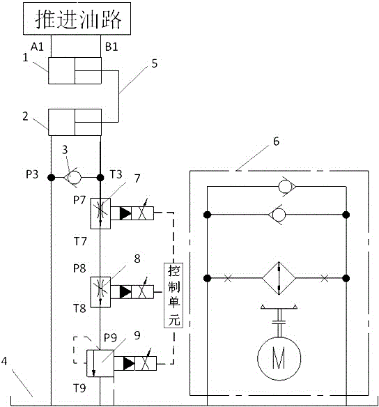
[0016] Such as figure 1 As shown, the present invention includes a propulsion oil cylinder 1, a thrust load oil cylinder 2, a reset check valve 3, a fuel tank 4, a connector 5, a slender hole electromagnetic proportional throttle valve 7, a thin edge electromagnetic proportional throttle valve 8 and an electromagnetic proportional overflow valve. flow valve 9; the rodless cavity of the propulsion cylinder 1 communicates with one oil port A1 of the propulsion oil circuit, the rod chamber of the propulsion cylinder 1 communicates with the other oil port B1 of the propulsion oil circuit, and the propulsion cylinder 1 and the thrust load cylinder 2 The protruding end of the piston rod is fixed through the connecting piece 5; the oil inlet P3 of the reset check valve 3 is connected with the rodless cavity of the thrust load cylinder 2 and the oil tank 4, and the oil outlet T...


PUM


Abstract

The invention discloses a thrust-load-simulation hydraulic system of a tunnel boring machine. A rodless cavity of a thrust oil cylinder is communicated with an oil opening of a thrust oil path, a rod cavity of the thrust oil cylinder is communicated with another oil opening of the thrust oil path, and the thrust oil cylinder is connected with a piston rod of a thrust-load oil cylinder; an oil inlet of a reset one-way valve is communicated with a large cavity of the thrust-load oil cylinder and an oil tank; one path of an oil outlet of the reset one-way valve is communicated with the rod cavity of the thrust-load oil cylinder, and the other path of the oil outlet of the reset one-way valve is connected with the oil tank after passing through a slender hole electromagnetic proportional throttle valve, a thin cutting edge electromagnetic proportional throttle valve and an electromagnetic proportional overflow valve; an oil inlet and an oil outlet of an oil and liquid air-cooling valve group are communicated with the oil tank. According to the thrust-load-simulation hydraulic system of the tunnel boring machine disclosed by the invention, the electromagnetic proportional throttle valve and the electromagnetic proportional overflow valve with different opening forms are connected in series and are subjected to uniform parameter adjustment, so that the setting of the thrust-load, the setting of rock-soil static pressure and the advance speed are considered in an unified manner to realize high-fidelity simulation of the thrust-load of the tunnel boring machine. The thrust-load-simulation hydraulic system is also suitable for other dynamic simulation occasions of linear thrust-load.

Description

technical field [0001] The invention relates to a load simulation hydraulic system, in particular to a tunnel boring machine thrust load simulation hydraulic system. Background technique [0002] The tunnel boring machine is a new type of tunnel construction machine. It cuts the rock and soil through the cutter head driven by the electric motor or hydraulic motor, and pushes forward under the action of the propulsion system. The conveyor belt transports the cut rock and soil, and the supporting system The excavated tunnel is supported, so that the entire section of the tunnel can be excavated at one time. The tunnel boring machine construction method integrates electromechanical and hydraulic control, and has the characteristics of fast, high-quality, safe, and environmentally friendly construction. It is the best choice for tunnel construction. [0003] The tunnel boring machine has a huge structure, complex system, high cost, and poor adaptability to different geological ...

Claims


Application Information

Patent Timeline
Patent Type & Authority Applications(China)
IPC IPC(8): F15B11/028F15B11/16F15B13/06
CPCF15B11/028F15B11/16F15B13/06
Inventor 龚国芳刘统张振饶云意王伟吴伟强杨华勇
Owner ZHEJIANG UNIV
Learn More