Oil charge buffering device of hydraulic gear-shifting gearbox clutch

A buffer device and clutch technology, applied in clutches, fluid-driven clutches, non-mechanical-driven clutches, etc., can solve problems such as large shift shocks, and achieve the effects of reducing shift shocks, quick oil return, and smooth integration

Inactive Publication Date: 2014-12-10
GUANGXI LIUGONG MASCH CO LTD
View PDF9 Cites 2 Cited by
  • Summary
  • Abstract
  • Description
  • Claims
  • Application Information

AI Technical Summary

Problems solved by technology

[0004] The object of the present invention is to provide an oil-filled buffer device for a hydraulic shift transmission clutch that solves the large problem of shift shock

Method used


Image

  • Oil charge buffering device of hydraulic gear-shifting gearbox clutch
  • Oil charge buffering device of hydraulic gear-shifting gearbox clutch
  • Oil charge buffering device of hydraulic gear-shifting gearbox clutch

Examples


Embodiment Construction

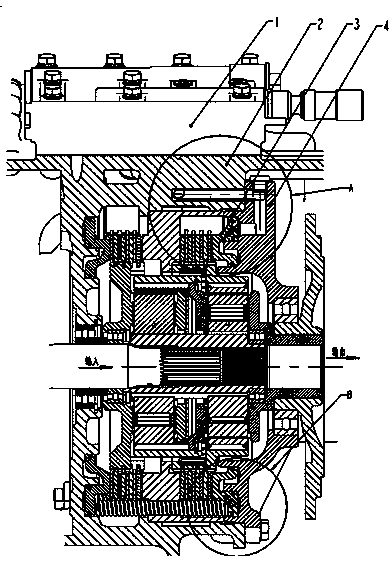
[0024] Such as figure 1 As shown, the casing 2 is fixed with an outer oil cylinder body 4, and the outer piston 3 cooperates with the outer oil cylinder body 4 to form an outer oil cylinder C. The outer piston 3 provides the clutch power of the clutch. The outer oil cylinder body 4 is provided with a ring-shaped groove, the outer piston 3 is provided with a ring-shaped boss, and the ring-shaped groove on the outer cylinder block 4 cooperates with the ring-shaped boss of the outer piston 3 to form an inner cylinder D; the outer cylinder Between the oil chamber of the outer oil cylinder of the cylinder body 4 and the oil chamber of the inner oil cylinder, a buffer control circuit composed of a check valve II and a damping valve I in parallel is arranged, and the check valve II is set as the check valve II when filling oil The oil is blocked when the lock is locked, and the oil is passed when the gear is off.

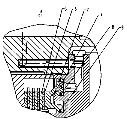
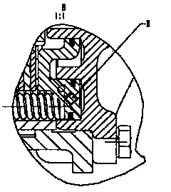
[0025] Such as figure 1 , 2 , 3, 5, 6, and 7, the innermost ring i...


PUM


Abstract

The invention provides an oil charge buffering device of a hydraulic gear-shifting gearbox clutch. A circular groove is formed in an outer oil cylinder, a circular boss is arranged on an outer piston, and the circular groove formed in the outer oil cylinder is matched with the circular boss arranged on the outer piston to form an inner oil cylinder. A buffering control loop is formed between an outer oil cylinder oil cavity of the outer oil cylinder and an oil cavity of the inner oil cylinder and formed by connecting a one-way valve and an orifice valve in parallel. The one-way valve is arranged in the mode that in the oil charging process, the one-way valve is locked and oil can not pass, and oil passes through the one-way valve in out-of-gear situation; the one-way valve and the orifice valve are arranged in the outer piston with the outer piston as a valve body, one end of the one-way valve and one end of the orifice valve are communicated with the oil cavity of the outer oil cylinder, and the other end of the one-way valve and the other end of the orifice valve are communicated with the oil cavity of the inner oil cylinder. The oil charge buffering device can achieve stable combination in gear shifting of the clutch, lower gear shifting impact, and achieve quick oil return in out-of-gear.

Description

technical field [0001] The invention belongs to the technical field of engineering machinery, in particular to a clutch applied to a loader hydromechanical shift gearbox. Background technique [0002] There are three shifting modes of construction machinery gearboxes: automatic shifting, semi-automatic shifting, and hydraulic-mechanical shifting. Hydraulic-mechanical shifting is the most widely used because of its low cost. The load-bearing torque of the shifting gearbox of construction machinery is large, and the reserve coefficient required by the clutch is relatively high. At present, the clutch of the gearbox is filled with oil too quickly, and the shifting impact is large. [0003] The clutch structure of the existing hydraulic shift gearbox is not equipped with a buffer device. When the gearbox is shifted, the clutch flushes oil too quickly, and the clutch is quickly combined. The torque is too large at the moment of combination, resulting in shift shock, uncomfortable...

Claims


Application Information

Patent Timeline
Patent Type & Authority Applications(China)
IPC IPC(8): F16D25/12
Inventor 高晓梁永华鄢万斌韦文静徐燚伟
Owner GUANGXI LIUGONG MASCH CO LTD
Why Eureka
Try Eureka