Oil return control mechanism and compressor

A technology of oil return control and compressor speed, which is applied in the field of compressors, can solve problems such as not being able to control the oil storage of compressors well, and achieve the effect of improving operation reliability

Pending Publication Date: 2021-02-19
ZHUHAI GREE REFRIGERATION TECH CENT OF ENERGY SAVING & ENVIRONMENTAL PROTECTION
View PDF1 Cites 1 Cited by
  • Summary
  • Abstract
  • Description
  • Claims
  • Application Information

AI Technical Summary

Problems solved by technology

[0007] One of the objectives of the present invention is to propose an oil return control mechanism and a compressor, which solves the technical problem that the oil return structure in the prior art cannot well control the oil storage inside the compressor when the compressor is running at high speed

Method used


Image

  • Oil return control mechanism and compressor
  • Oil return control mechanism and compressor
  • Oil return control mechanism and compressor

Examples


Embodiment 1

[0039] This embodiment describes in detail the first preferred implementation of the oil return control mechanism 21 of the present invention.

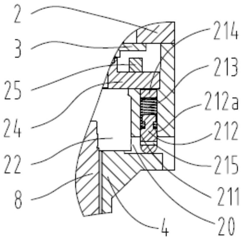
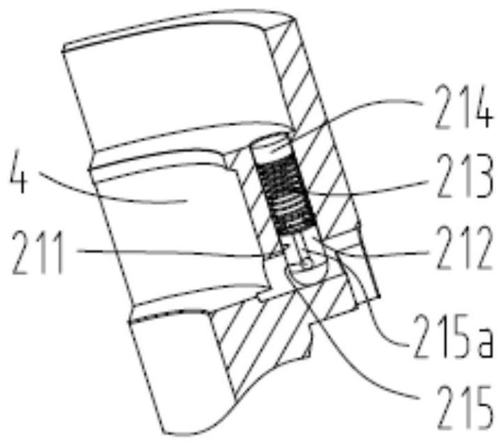
[0040] The oil return control mechanism 21 of this embodiment includes a housing part 211, a regulating valve 212 and an elastic member 213, such as Figure 1~5 shown. Preferably, the regulating valve 212 is provided with a channel assembly, and the channel assembly communicates with the oil return channel 20 on the upper support mechanism 4 . Preferably, the regulating valve 212 and the elastic member 213 are located in the housing portion 211 and can move along the axial direction of the housing portion 211 based on the compressor rotation speed, and the regulating valve 212 and the elastic member 213 have a second function of closing the oil return passage 20 One state and the second state of opening the oil return passage 20; and when the regulating valve 212 and the elastic member 213 are in the first state, the lubricating oil ...

Embodiment 2

[0053] This embodiment describes in detail the second preferred embodiment of the oil return control mechanism 21 of the present invention.

[0054] The difference between this embodiment and Embodiment 1 lies in the structure of the channel assembly on the regulating valve 212 . In this embodiment, only the parts different from those in Embodiment 1 are described in detail, and the same parts are not described again.

[0055] According to a preferred embodiment, the channel assembly includes an annular groove 218 and a second communication groove 218a, such as Figures 9 to 12 shown. Preferably, the annular groove 218 located in the circumferential direction of the regulating valve 212 communicates with the oil return passage 20 on the upper support mechanism 4; the second communication groove 218a communicates with the annular groove 218 and passes through the valve end surface 212a in the axial direction. The preferred technical solution of this embodiment said that the a...

Embodiment 3

[0059] This embodiment describes in detail the third preferred embodiment of the oil return control mechanism 21 of the present invention.

[0060] The difference between this embodiment and embodiment 1 or embodiment 2 lies in the arrangement position of the receiving portion 211 and the sealing member above the elastic member 213 . In this embodiment, only the parts different from those in Embodiment 1 or Embodiment 2 are described in detail, and the same parts are not described again.

[0061] According to a preferred embodiment, the receiving portion 211 is located on the upper supporting mechanism 4 and the cover plate 24, such as Figure 7 shown. Preferably, the oil return control mechanism 21 further includes an O-ring seal 216, and the O-ring seal 216 is located on the outer side of the housing portion 211 and between the upper support mechanism 4 and the cover plate 24, such as Figure 7 shown. The preferred technical solution of this embodiment can be sealed by th...


PUM


Abstract

The invention discloses an oil return control mechanism and a compressor, relates to the technical field of compressors, and solves the problem that an oil return structure in the prior art cannot well control the oil storage amount in the compressor when the compressor operates at a high speed. An adjusting valve and an elastic piece of the oil return control mechanism are located in a containingpart and can move in the axial direction of the containing part based on the rotating speed of the compressor, and the adjusting valve and the elastic piece have the first state of closing an oil return channel and the second state of opening the oil return channel. When the adjusting valve and the elastic piece are in the first state, lubricating oil is recycled to an oil pool through a channelassembly; when the adjusting valve and the elastic piece are in the second state, the lubricating oil is recycled to the oil pool through the oil return channel or the oil return channel and the channel assembly. When the compressor operates at a low rotating speed, the lubricating oil is recycled to the oil pool through the channel assembly, and when the compressor operates at a high rotating speed, the lubricating oil is recycled to the oil pool through the oil return channel or the oil return channel and the channel assembly, and therefore the operation reliability of the compressor at thesame rotating speed is improved.

Description

technical field [0001] The invention relates to the technical field of compressors, in particular to an oil return control mechanism and a compressor including the oil return control mechanism. Background technique [0002] Scroll compressors are widely used in the fields of air conditioners and heat pumps, and mainly include components such as casings, compression mechanisms, support mechanisms, drive mechanisms, working fluid suction pipes, and working fluid discharge pipes. Wherein, the compression mechanism includes a moving scroll component and a fixed scroll component; the driving mechanism includes a stator assembly, a crankshaft and a rotor assembly. The crankshaft drives the movable scroll, and since the movable scroll is provided with an anti-rotation mechanism, the movable scroll can perform translational rotation relative to the fixed scroll. The volume of the compression chamber defined by the spiral scroll of the fixed scroll part and the spiral scroll of the ...

Claims


Application Information

Patent Timeline
Patent Type & Authority Applications(China)
IPC IPC(8): F04C29/02F04C18/02F04C23/02
CPCF04C18/0215F04C23/02F04C29/021F04C29/028
Inventor 徐嘉单彩侠杨震郭求和
Owner ZHUHAI GREE REFRIGERATION TECH CENT OF ENERGY SAVING & ENVIRONMENTAL PROTECTION
Why Eureka
Try Eureka