High-pressure oil pipe pressure relief circuit and method with quick-change connectors

A high-pressure oil pipe and pressure relief technology, which is applied in the direction of mechanical equipment, fluid pressure actuation devices, fluid pressure actuation system components, etc., can solve the problems of hydraulic oil environmental pollution, hydraulic oil waste, and inability to connect high-pressure joints, etc., to achieve increased The effect of fast oil return speed

Pending Publication Date: 2018-12-07
湖南湘一环境科技有限公司
View PDF6 Cites 1 Cited by
  • Summary
  • Abstract
  • Description
  • Claims
  • Application Information

AI Technical Summary

Problems solved by technology

In the next use, connect the main engine and the hydraulic control system through the quick-change joint of the high-pressure oil pipe. Since there is still high-pressure oil in the high-pressure oil pipe, the two ends of the high-pressure joint cannot be connected.
Physical methods must be used to release the high-pressure oil remaining in the high-pressure oil pipe, which will not only cause the pollution of the hydraulic oil to the environment, but also cause a waste of hydraulic oil

Method used


Image

  • High-pressure oil pipe pressure relief circuit and method with quick-change connectors
  • High-pressure oil pipe pressure relief circuit and method with quick-change connectors

Examples


Embodiment 1

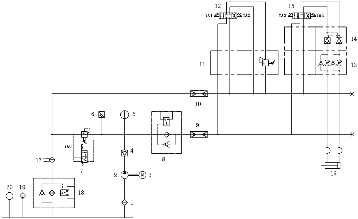
[0032] Provide a high-pressure oil pipe pressure relief circuit with a quick-change joint, including an oil inlet module, a first quick-change joint 9, a first reversing valve 12, a second quick-change joint 10 and an oil return module connected in sequence; wherein, The oil inlet module includes an oil tank 1, an oil pump 2, a check valve 4 and a fine filter 8 connected sequentially along the oil inlet route. The oil pump 2 is also connected to the motor 3, the check valve 4 is also connected to the pressure gauge 5, and the fine filter 8 The other end is connected with the left side of the first quick-change joint 9, and the first quick-change joint 9 is located at the oil inlet circuit, that is, connected with the high-pressure oil pipe. The oil return module includes a radiator 17, an oil return filter 18 and an oil tank 1 sequentially connected along the oil return route, and the oil tank 1 is also connected with an oil return filter 19 and an oil mark 20 respectively, and...

Embodiment 2

[0044] The difference between Embodiment 2 and Embodiment 1 is that the pressure relief circuit also includes a relief valve 11 connected to the first reversing valve 12 and a hopper control module, and the hopper control module includes a second reversing valve 15 connected in sequence, Two-way hydraulic lock 14, double one-way throttle valve 13 and material turning hydraulic cylinder 16. The relief valve 11 is used to adjust the high pressure of the oil inlet circuit to a set constant pressure. The hopper control module is used to control the rise and fall of the hopper further.

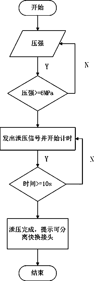
[0045]During normal operation, the pressure in the oil pipe of the main engine is 16MPa, but only 6MPa is required when the hopper is working, and the working time of the hopper is less than 1% of the working time of the whole machine, so the pressure in the oil pipe is only reduced during the working time of the hopper , which can save costs without affecting the normal operation of the whole mac...


PUM


Abstract

The invention belongs to the technical field of urban environmental sanitary equipment and particularly relates to a high-pressure oil pipe pressure relief circuit with quick-change connectors. The high-pressure oil pipe pressure relief circuit with the quick-change connectors comprises an oil feeding module, a first quick-change connector, a first reversing valve, a second quick-change connectorand an oil return module, wherein the oil feeding module, the first quick-change connector, the first reversing valve, the second quick-change connector and the oil return module are sequentially connected. An electromagnetic overflow valve and a pressure transmitter are arranged between the oil feeding module and the oil return module. Through additional arrangement of the reversing valve, an oilreturn path is changed and avoids the electromagnetic overflow valve, and therefore the oil return speed can be greatly improved; besides, a prompting function is provided, an operator can separate amain machine and a hydraulic control system according to prompt, and the situation that due to misoperation, the high-pressure oil pipe is not completely decompressed, and environmental pollution andresource waste are caused is avoided.

Description

technical field [0001] The invention belongs to the technical field of urban environmental sanitation equipment, and more specifically relates to a high-pressure oil pipe pressure relief circuit and a pressure relief method provided with quick-change joints. Background technique [0002] With the progress and development of society, domestic waste is increasing. In order to keep the living environment clean and reduce the spread of diseases, it is necessary to deal with domestic waste. Especially in my country, with the advancement of urbanization, the integration of urban and rural domestic waste management is becoming more and more important. Significantly important, so products for waste disposal have also developed accordingly. In order to make garbage disposal less landfill, high fuel value for power generation, pollution-free transshipment, and high transportation efficiency, compressing domestic waste before transshipment is an internationally recommended waste disposa...

Claims


Application Information

Patent Timeline
Patent Type & Authority Applications(China)
IPC IPC(8): F15B13/02F15B21/02
CPCF15B13/02F15B21/005F15B21/02
Inventor 王果年廖建红廖震寰何志强夏中正
Owner 湖南湘一环境科技有限公司
Why Eureka
Try Eureka