
Calibration device for detecting vacuum gauges with relative errors of indicating values no less than 30%

A technology of relative error and calibration device, applied in the direction of measuring device, measuring fluid pressure, instruments, etc., can solve the problems of inability to perform calibration at any time, inconvenient production, errors, etc., and achieve the effect of low measurement environment requirements, low cost, and simple operation.

Inactive Publication Date: 2014-12-10
XIANGTAN ELECTRIC MFG CORP LTD
View PDF3 Cites 3 Cited by
  • Summary
  • Abstract
  • Description
  • Claims
  • Application Information

AI Technical Summary

Problems solved by technology

At present, the motor is the leading product of our company and the relative error of the indication value of the resistance vacuum gauge used is 30%. Since the company does not have a verification device, and the measurement of the provincial and municipal metrology departments is blank, it is necessary to send someone to send the vacuum gauge to Beijing, China. It takes more than half a month for the calibration of the metrology institute, and the instrument may be damaged at any time on the way. If there is a problem with the vacuum gauge during the calibration period, it cannot be calibrated at any time, which brings great inconvenience to production; and our company uses The relative error of the indication value of the vacuum gauge is 30%, and the high-precision level calibration device of the China Institute of Metrology in Beijing is not required

Method used


Image

  • Calibration device for detecting vacuum gauges with relative errors of indicating values no less than 30%
  • Calibration device for detecting vacuum gauges with relative errors of indicating values no less than 30%
  • Calibration device for detecting vacuum gauges with relative errors of indicating values no less than 30%

Examples


Embodiment Construction

[0015] The present invention will be further described below in conjunction with the accompanying drawings.

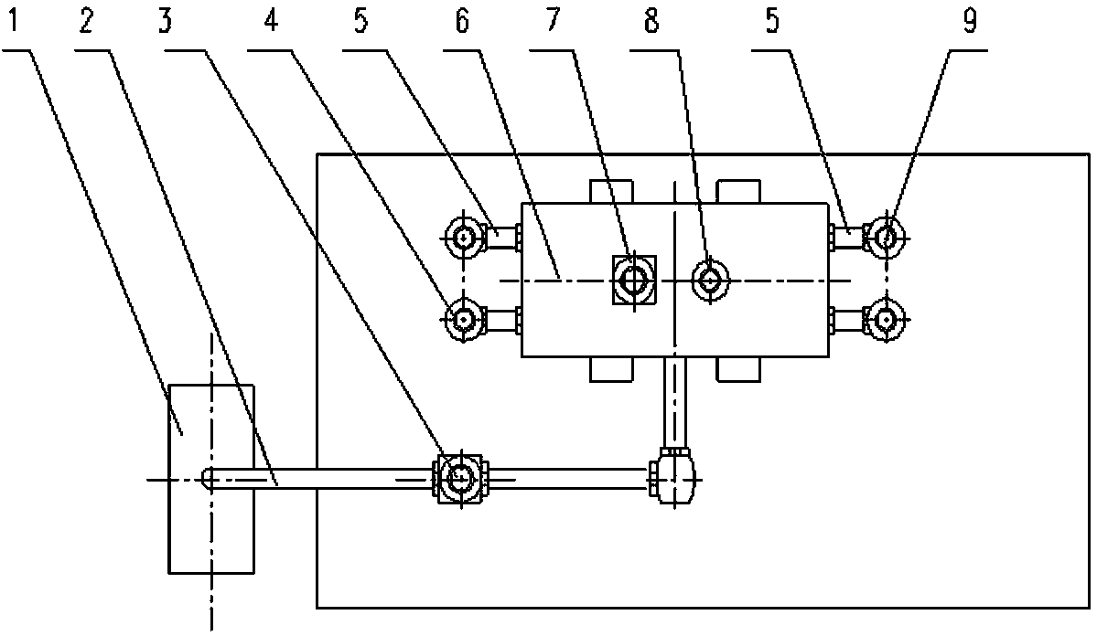
[0016] Such as figure 1 As shown, the present invention includes a vacuum pump 1, a standard vacuum gauge 4, a calibrated vacuum gauge 9, a calibration chamber 6 and a connecting pipe 5. The shape of the calibration chamber 6 is a cylinder with a height-to-inner diameter ratio of 1 to 3 / 1, two connecting pipes 5 are welded at both ends of the calibration chamber 6, and a valve 7 is welded in the middle of the side of the calibration chamber 6 , fine-tuning valve 8 and the connection interface, the connection interface is connected with the vacuum pump 1 through the pipeline 2, and the control valve 3 is arranged on the pipeline 2. The standard vacuum gauge 4 and the calibrated vacuum gauge 9 are respectively installed at the port of the connecting pipe 5 .

[0017] The principle of the present invention is as follows: the present invention adopts the principle of dyn...


PUM


Abstract

The invention discloses a calibration device for detecting vacuum gauges with relative errors of indicating values no less than 30%. The calibration device comprises a vacuum pump, a standard vacuum gauge, a calibrated vacuum gauge, a calibration room and connection pipelines. The vacuum pump is connected with the calibration room through a pipeline provided with a control valve, the connection pipeline is communicated with the calibration room, and the standard vacuum gauge and the calibrated vacuum gauge are mounted at ports of the connection pipelines. The calibration device is simple in structure, convenient to operate and low in cost; due to the fact that the plurality of connection pipelines are welded to two ends of the calibration room, a plurality of calibrated vacuum gauges can be detected at the same time, and accordingly detection efficiency is improved.

Description

technical field [0001] The invention relates to a calibration device for detecting a vacuum gauge whose relative error of indication value is not less than 30%. Background technique [0002] Vacuum gauge is a monitoring instrument during the process of vacuum impregnation of motors. Whether it is accurate or not directly affects the effect of impregnation and is related to the quality of the motor. Motor manufacturing process documents stipulate: In the production process of motors above 6kv, the stator coil insulation must be strictly vacuum-impregnated during the manufacturing process. Vacuum gauges are used to monitor the vacuum during the vacuum impregnation process. Whether the vacuum gauge is accurate or not is directly related to the effect of dipping paint. If the indication value of the vacuum gauge is inaccurate, the air in the air gap between the stator and the coil will not be completely removed, resulting in insufficient impregnation. When such a motor is in ...

Claims


Application Information

Patent Timeline
Patent Type & Authority Applications(China)
IPC IPC(8): G01L27/00
Inventor 徐高朱琳陈清理万瑞华陈磊廖庆新
Owner XIANGTAN ELECTRIC MFG CORP LTD
Learn More