Optical lens vertical drive

A technology for optical lenses and drives, applied in optics, optical components, instruments, etc., can solve the problems of low precision of the vertical drives of optical lenses, friction, large contact area between hard alloy hemispheres and precision screws, etc., and achieve reduction The effect of return difference, small active area, high sensitivity and precision

Active Publication Date: 2016-05-11
成都科信达实业有限公司
View PDF4 Cites 0 Cited by
  • Summary
  • Abstract
  • Description
  • Claims
  • Application Information

AI Technical Summary

Problems solved by technology

[0002] At present, the vertical driver of the optical lens is generally driven by a stepping motor. The stepping motor is connected to the precision screw through a coupling. The screw drives the carbide hemisphere to move along the positive and negative directions of the axis of the precision screw to adjust the frame, but now the diameter of the carbide hemisphere is usually processed to be the same as that of the precision screw, so that the upper end surface of the carbide hemisphere is completely It is fixed at the end of the precision screw to firmly fix the carbide hemisphere, but the contact area between the carbide hemisphere and the precision screw is too large by this connection method, resulting in greater friction, which eventually leads to the vertical drive of the optical lens. Not very accurate

Method used


Image

  • Optical lens vertical drive

Examples


Embodiment 1

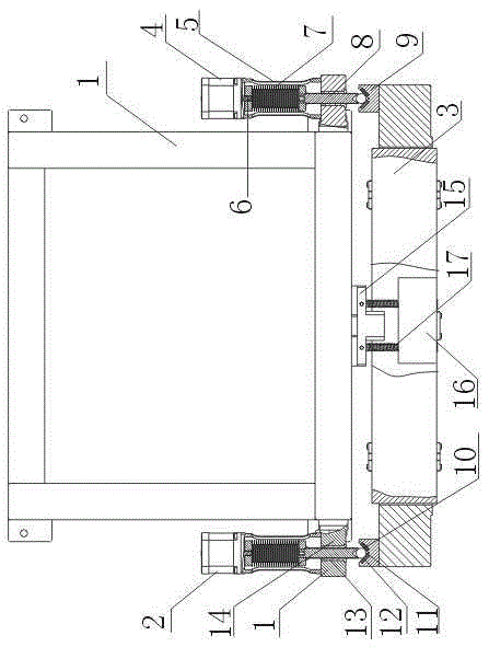
[0015] Such as figure 1 As shown, the optical lens vertical driver includes a support frame 1, an adjustment device 2 fixed on both sides of the support frame 1, and a mirror frame 3 fixed on the bottom of the support frame 1 through a universal ball head 15; the adjustment device 2 includes a step Motor 4, the casing 5 that is connected with stepper motor 4, described casing 5 is cavity structure, also comprises the telescopic coupling 7 that is arranged in casing 5 cavity structure and is connected with the output shaft 6 of stepper motor 4 and The precision screw 8 connected to the other end of the telescopic coupling 7 also includes positioning seats 9 located on the upper surfaces of both ends of the frame 3, and the ends of the precision screw 8 fall on the positioning seats 9; wherein the positioning seats 9 are V-shaped The positioning seat, the end of the precision screw 8 has a V-shaped groove 10, and also includes a hard alloy sphere 11, and the hard alloy sphere 11...

Embodiment 2

[0018] In this embodiment, on the basis of Embodiment 1, the telescopic coupling 7 is a bellows coupling.

[0019] In this embodiment, the use of the welded bellows coupling can greatly reduce the backstroke difference generated during the adjustment process of the vertical drive of the optical lens and keep the backstroke difference stable.

Embodiment 3

[0021] On the basis of Embodiment 1 or Embodiment 2, this embodiment also includes a screw sleeve 13 fixed on the precision screw rod 8, and a connecting block 14 connected to the screw sleeve 13, and the end of the shell 5 is fixed on the connecting block. The upper end of 14, connecting piece 14 is welded on the side wall of support frame 1.

[0022] In this embodiment, the screw sleeve 13 covering the precision screw 8 protects the precision screw 8 so that the precision screw 8 is not easy to be worn. The connecting block 14 is welded on the side wall of the support frame 1, which ensures that the precision screw rod 8 will not fall off from the support frame 1 due to the vibration of the stepping motor 4 when it moves.


PUM


Abstract

The invention discloses an optical lens vertical driver. The optical lens vertical driver comprises a supporting frame, adjusting devices which are fixed on bilateral sides of the supporting frame and a mirror frame which is fixed at the bottom of the supporting frame through universal balls; each adjusting device comprises a stepping motor and an outer casing which is connected with the stepping motor; the outer casings are in empty chamber structures; each adjusting device also comprises an extensible coupler which is arranged inside the outer casing empty chamber structure and connected with an output shaft of the corresponding stepping motor, a precise screw which is connected with the other end of the extensible coupler, a positioning base, a hard alloy sphere and a hard alloy gasket; the positioning bases are arranged on the upper surfaces at two ends of end of the mirror frame; the hard alloy gaskets are embedded on bilateral sides of the V-shaped positioning bases; tail ends of the precise screws are arranged on the positioning bases; the positioning bases are V-shaped positioning bases; the tail ends of the precise screws are provided with V-shaped grooves; the hard alloy spheres are in contact with bilateral side lines of the V-shaped grooves; lower sphere bodies of the hard alloy spheres are arranged inside the V-shaped positioning bases. The precise screws can drive the hard alloy spheres to vertically move to achieve alight adjustment of the mirror frame.

Description

technical field [0001] The invention relates to a vertical driver for optical mirrors, in particular to a vertical driver for precision optical mirrors. Background technique [0002] At present, the vertical driver of the optical lens is generally driven by a stepping motor. The stepping motor is connected to the precision screw through a coupling. The screw drives the carbide hemisphere to move along the positive and negative directions of the axis of the precision screw to adjust the frame, but now the diameter of the carbide hemisphere is usually processed to be the same as that of the precision screw, so that the upper end surface of the carbide hemisphere is completely It is fixed at the end of the precision screw to firmly fix the carbide hemisphere, but the contact area between the carbide hemisphere and the precision screw is too large by this connection method, resulting in greater friction, which eventually leads to the vertical drive of the optical lens. Not very...

Claims


Application Information

Patent Timeline
Patent Type & Authority Patents(China)
IPC IPC(8): G02B7/00
Inventor 范盛强
Owner 成都科信达实业有限公司
Why Eureka
Try Eureka