Precision electric adjustment frame

A kind of electric adjustment frame, precise technology, applied in the machine/bracket, installation, optics and other directions, can solve the problems of the precision electric adjustment frame is not high, the return difference is large, etc., to achieve high accuracy, reduce the effect of return difference

Active Publication Date: 2016-03-30
成都科信达实业有限公司
View PDF6 Cites 0 Cited by
  • Summary
  • Abstract
  • Description
  • Claims
  • Application Information

AI Technical Summary

Problems solved by technology

[0003] In order to solve the problem that the accuracy of the precision electric adjustment frame is not high, and the structure in the form of a feather key is used as a coupling to cause a large return stroke difference, the present invention provides a precision electric adjustment frame

Method used


Image

  • Precision electric adjustment frame

Examples


Embodiment 1

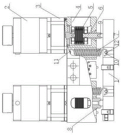
[0014] Such as figure 1 As shown, the precision electric adjustment frame includes a mirror frame 1, a connecting block 4, and driving components fixed on both sides of the connecting block 4. The driving components include a stepping motor 2 and a miniature planetary gear reducer 3 connected to the stepping motor 2. , wherein the connection block 4 is a cavity structure, and also includes an elastic coupling 5 arranged in the cavity structure of the connection block 4 and connected to the output shaft of the miniature planetary gear reducer 3, and also includes an output of the elastic coupling 5 The end of the precision screw 6 connected to each other, the end of the precision screw 6 falls on the upper surface of the picture frame 1, and also includes a spring 7 connected to the connection block 4 at one end and connected to the picture frame 1 at the other end; the end of the precision screw 6 has a conical groove A8 , also includes a cemented carbide half-steel ball 9 fix...

Embodiment 2

[0017] The elastic coupling 5 is a welded bellows elastic coupling.

[0018] In this embodiment, the precision electric adjustment frame adopts the welded bellows coupling, which can greatly reduce the backstroke difference generated during the adjustment process of the precision electric adjustment frame and maintain the stability of the backstroke difference.

Embodiment 3

[0020] In this embodiment, on the basis of embodiment 1 or embodiment 2, the spring 7 is an extension spring, the inner wall of the connecting block 4 is fixed with a screw A11, the upper hook of the extension spring is covered on the screw A11, and the Bottom has hole 10, and the sidewall of hole 10 is fixed with screw B12, and the lower hook of extension spring is enclosed within on the screw B12.

[0021] In this embodiment, one end of the extension spring is fixed on the connecting block 4, and the other end is fixed in the frame 1. When the frame 1 moves down or up under the action of the precision screw 6, the extension spring will stretch or shrink , when the motor stops moving, the active force generated by the extension spring will adjust the mirror frame 1 to return to the original position.


PUM


Abstract

The invention discloses a precise electric adjusting frame. The precise electric adjusting frame comprises a mirror frame, a connecting block and driving components which are fixed on bilateral sides of the connecting block; each driving component comprises a stepping motor and a mini-sized planetary gear reducer connected with the stepping motor; the connecting block is of an empty chamber structure. The precise electric adjusting frame also comprises an elastic coupler which is arranged inside the empty chamber structure of the connecting block and connected with an output shaft of a mini-sized planetary gear reducer, a precise screw which is connected with an output end of the elastic couple, a spring with one end being connected with the connecting block and the other end being connected with the mirror frame and a hard alloy semi-steel ball which is fixed inside the circular groove A through line contact; the tail end of the precise screw is arranged on the upper surface of the mirror frame; the tail end of the precise screw is provided with a circular cone groove A; the bottom of the hard alloy semi-steel ball is arranged on the upper surface of the mirror frame. According to the precise electric adjustment frame, the precise screw is connected with the extensible coupler and fine adjustment of the mirror frame is achieved due to vertical movement of the precise screw under the action of an electric motor.

Description

technical field [0001] The invention relates to a precision electric adjustment mount, in particular to a low-return precision electric adjustment mount. Background technique [0002] At present, the precision electric adjustment frame is generally driven by a stepping motor. The stepping motor is connected with the precision screw through a coupling. The precision screw acts on the frame, and the stepping motor drives the precision screw to move along the positive and negative directions of its axis to adjust the frame. , but now the structure in the form of a feather key is usually used as a coupling. The structure in the form of a feather key acts as a coupling to make the return stroke difference large. Furthermore, the current precision electric adjustment mounts are not very accurate, and cannot meet the adjustment requirements with an accuracy lower than 1 micron. Contents of the invention [0003] In order to solve the problem that the accuracy of the precision e...

Claims


Application Information

Patent Timeline
Patent Type & Authority Patents(China)
IPC IPC(8): G02B7/00F16M11/04F16M11/18
Inventor 范盛强
Owner 成都科信达实业有限公司
Why Eureka
Try Eureka