Low backstroke difference precision electric adjustment frame

A technology of electric adjustment frame and return difference, applied in installation, optics, instruments, etc., can solve problems such as large return difference, and achieve the effects of reducing damage, small effect area, high sensitivity and accuracy

Active Publication Date: 2016-06-29
成都科信达实业有限公司
View PDF10 Cites 0 Cited by
  • Summary
  • Abstract
  • Description
  • Claims
  • Application Information

AI Technical Summary

Problems solved by technology

[0003] In order to solve the problem that the structure in the form of a feather key is used as a coupling to cause a large return stroke difference, the present invention provides a precision electric adjustment frame with a low return stroke difference

Method used


Image

  • Low backstroke difference precision electric adjustment frame

Examples


Embodiment 1

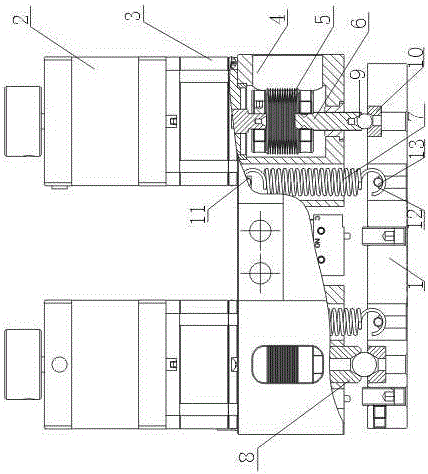
[0015] like figure 1 As shown, the precision electric adjustment frame with low backlash difference includes a mirror frame 1, a connecting block 4, and driving components fixed on both sides of the connecting block 4. The driving components include a stepping motor 2 and a miniature planet connected to the stepping motor 2. The gear reducer 3, wherein the connection block 4 is a cavity structure, also includes an elastic coupling 5 arranged in the cavity structure of the connection block 4 and connected to the output shaft of the miniature planetary gear reducer 3, and also includes an elastic coupling The precision screw 6 connected to the output end of the device 5, the end of the precision screw 6 falls on the upper surface of the mirror frame 1, and also includes a spring 7 connected to the connecting block 4 at one end and connected to the mirror frame 1 at the other end.

[0016] In this embodiment, the precision screw 6 is connected to one end of the elastic coupling 5...

Embodiment 2

[0018] In this embodiment, on the basis of Embodiment 1, the elastic coupling 5 is a welded bellows coupling.

[0019] In this embodiment, the low backstroke difference precision electric adjustment frame adopts a welded bellows coupling, which can greatly reduce the backstroke difference and maintain the stability of the backstroke difference.

Embodiment 3

[0021] In this embodiment, on the basis of embodiment 1 or embodiment 2, the end of the precision screw 6 is provided with a conical groove A8, and the upper surface of the mirror frame 1 is provided with a conical groove B10 corresponding to the conical groove A8; The cemented carbide steel ball 9, the upper ball of the cemented carbide steel ball 9 is in line contact with the conical groove A8, and the lower ball of the cemented carbide steel ball 9 falls in the conical groove B10.

[0022] In this embodiment, the hard alloy steel ball 9 is arranged in the conical groove A8 that the end of the precision screw rod 6 has, and the lower sphere of the hard alloy steel ball 9 falls in the conical groove B10, so that the precision screw rod 6 moves up and down. Drive cemented carbide steel ball 9 to move up and down when moving and then realize the fine-tuning of picture frame 1, and because cemented carbide steel ball 9 acts on the side wall of conical groove B10 with the mode of ...


PUM


Abstract

The invention describes a precision electric adjustment frame with low backstroke difference, which includes a mirror frame, a connecting block, and driving components fixed on both sides of the connecting block. The driving component includes a stepping motor and a miniature planetary gear reducer connected with the stepping motor. The connection block is a cavity structure, and also includes an elastic coupling arranged in the cavity structure of the connection block and connected to the output shaft of the miniature planetary gear reducer, and also includes a precision screw connected to the output end of the elastic coupling, The end of the precision screw falls on the upper surface of the picture frame, and also includes a spring with one end connected to the connection block and the other end connected to the picture frame. In this embodiment, the setting of the miniature planetary gear reducer can make the precision electric adjustment frame with low backlash difference obtain high resolution. The welded bellows coupling can greatly reduce the return difference generated by the electric adjustment frame during the adjustment process and keep the return difference stable.

Description

technical field [0001] The invention relates to a precision electric adjustment mount, in particular to a precision electric adjustment mount with low backstroke difference. Background technique [0002] At present, the electric adjustment frame is generally driven by a stepping motor. The stepping motor is connected with a precision screw through a coupling. The precision screw acts on the frame, and the stepping motor drives the precision screw to move along the positive and negative directions of its axis to adjust the frame. However, the structure in the form of a feather key is usually used as the coupling at present. The structure in the form of a feather key acts as a coupling to make the return stroke difference large. Contents of the invention [0003] In order to solve the problem that the structure in the form of a feather key is used as a shaft coupling to cause a large return distance difference, the present invention provides a precision electric adjustment ...

Claims


Application Information

Patent Timeline
Patent Type & Authority Patents(China)
IPC IPC(8): G02B7/00
Inventor 范盛强
Owner 成都科信达实业有限公司
Why Eureka
Try Eureka