Method for identifying dust and pocking marks on surface of big-caliber optical element

An optical element, a large-diameter technology, applied in the field of pattern recognition, can solve the problems of no automatic identification of pits and dust, difficult to distinguish, etc., to achieve high classification accuracy and avoid complex processes.

Inactive Publication Date: 2014-12-10
LASER FUSION RES CENT CHINA ACAD OF ENG PHYSICS +1
View PDF2 Cites 13 Cited by
  • Summary
  • Abstract
  • Description
  • Claims
  • Application Information

AI Technical Summary

Problems solved by technology

[0003] At present, there are many methods for surface damage detection of large-aperture optical components, but none of them have the function of automatic identification of pitting and dust. Pitting and dust are similar in shape and difficult to distinguish, and pitting and dust are the damage information that inspectors are most concerned about. One, so fast and efficient identification of pitting and classification is very important

Method used


Image

  • Method for identifying dust and pocking marks on surface of big-caliber optical element
  • Method for identifying dust and pocking marks on surface of big-caliber optical element
  • Method for identifying dust and pocking marks on surface of big-caliber optical element

Examples


Embodiment Construction

[0024] In order to make the object, technical solution and advantages of the present invention clearer, the present invention will be described in further detail below in conjunction with specific embodiments and with reference to the accompanying drawings.

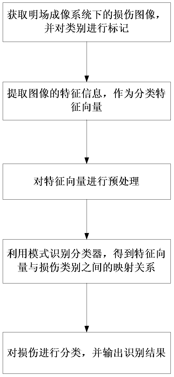
[0025] figure 1 It is a flow chart of the method for identifying dust and pitting on the surface of a large-diameter optical element of the present invention, as figure 1 As shown, the method for identifying dust and pitting on the surface of the large-diameter optical element includes the following steps:

[0026] Step 1: Use an image acquisition device to collect surface damage images of large-aperture optical components under bright field conditions as sample images, and mark the damage category corresponding to each sample image;

[0027] In an embodiment of the present invention, the image acquisition device includes a microscope lens and an area array CCD camera, and examples of bright field images of dust and pits...


PUM


Abstract

The invention discloses a method for identifying dust and pocking marks on a surface of a big-caliber optical element. The method comprises the following steps of: utilizing an image acquisition device to acquire surface damage images of the big-caliber optical element under the condition of a light field to serve as sample images, and marking the damage type corresponding to each sample image; extracting characteristic vectors of the acquired sample images; performing pre-treatment on the obtained characteristic vectors; regarding the characteristic vectors after the pre-treatment as input variables of a mode identification classifier, and regarding corresponding damage type labels as output variables of a mode identification classifier so as to obtain a mapping relationship between the input variables and the output variables; identifying the damage types of the tested samples based on the mapping relationship, and outputting the identification result. The mode identification method is adopted to start from the texture characteristics of images in the light field, so that the automatic judgment problem of the dust and the pocking marks on the surface of the big-caliber optical element is solved.

Description

technical field [0001] The invention relates to the technical field of pattern recognition, in particular to a method for recognizing dust and pitting on the surface of a large-diameter optical element. Background technique [0002] Large-aperture optical components are widely used in optical-mechanical systems with high optical flux density represented by modern laser technology, in the field of low-light imaging represented by infrared night vision optical systems, and in the field of semiconductor processing and manufacturing represented by wafer surface processing and detection. . Large-aperture optical components will produce various defects in the process of production, processing, cleaning and transportation, such as pitting, scratches, wrapping, deliquescence, mildew, fibers, water stains, scratches, etc. These surface defects All defects will affect the performance of the optical system, and different types and sizes of defects have different effects on the system....

Claims


Application Information

Patent Timeline
Patent Type & Authority Applications(China)
IPC IPC(8): G06K9/46G06K9/62
Inventor 熊召刘长春袁晓东周海徐旭陈海平陶显张正涛张峰史亚莉
Owner LASER FUSION RES CENT CHINA ACAD OF ENG PHYSICS
Why Eureka
Try Eureka