
Anti-spin aircraft structure

An aircraft structure and anti-spin technology, which can be used in seaplanes, aircraft stability, aircraft parts, etc., and can solve problems such as insecurity

Active Publication Date: 2016-08-24
ICON AIRCRAFT
View PDF11 Cites 0 Cited by
  • Summary
  • Abstract
  • Description
  • Claims
  • Application Information

AI Technical Summary

Problems solved by technology

correspondingly, if the aircraft is not certified for spin recovery, it is assumed that the spin is irrecoverable and it is considered unsafe to perform a spin in that aircraft

Method used


Image

  • Anti-spin aircraft structure
  • Anti-spin aircraft structure
  • Anti-spin aircraft structure

Examples


Embodiment Construction

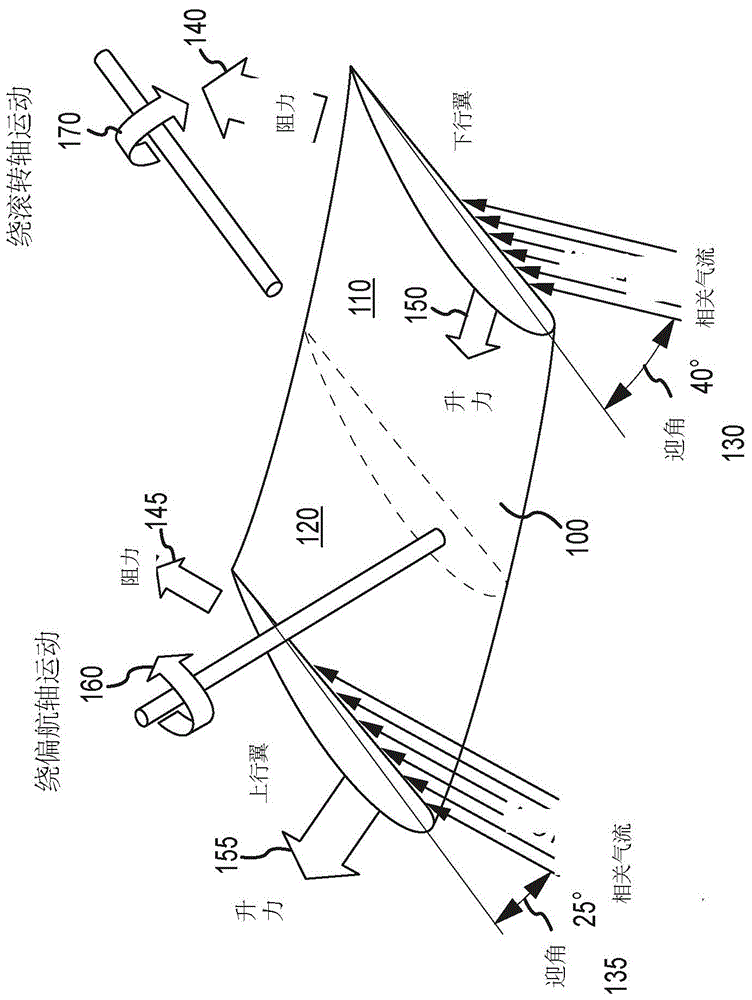
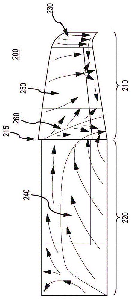
[0031] Disclosed below by way of example is a novel construction of the aerodynamic characteristics of a fully spin-resistant aircraft. According to one embodiment of the present invention, various aerodynamic techniques interact to obtain against an aircraft entering a spin throughout the entire range of flight tests set forth in the United States Aviation Administration (FAA) regulations. One aspect of the present structure / combination is the gusseted wing design, which employs multiple proprietary airfoils across the span of the wing that control stall development to produce a stable stall cell. This discontinuity at the leading edge of the wing delineates the wing into two distinct regions. The outboard (away from the centerline) section of a gusseted wing has a different airfoil with drooping leading edge than the inboard section of the wing, which causes the outboard section to stall later than the wing as the angle of attack increases medial segment. Because the ailer...


PUM


Abstract

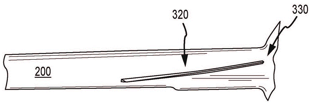
The invention discloses a structure and a system for making an aircraft anti-spin. Aircraft resistance to spin is accomplished by confining the stall cells to the wing region (220) adjacent to the fuselage and away from the wingtips (210). Wing features that facilitate this constraint include, but are not limited to, one or more folds (215), stall bars (320), vortex generators (630), wing twist (510-550), wing sweep, and horizontal stability device. The aircraft structural features presented by the invention, alone or in combination, render the aircraft anti-spin by constraining the stall cells, which allows the control surfaces of the aircraft to remain operable to control the aircraft.

Description

[0001] related application [0002] This application is related to and claims the benefit of U.S. Nonprovisional Patent Application 13 / 946,572, filed July 19, 2013, and U.S. Provisional Patent Application No. 61 / 674,267, filed July 20, 2002, both of which are incorporated by reference The entire text is hereby incorporated for all purposes as if fully set forth herein. technical field [0003] Embodiments of the present invention generally relate to aerodynamic techniques intended to prevent an aircraft from being able to enter a spin, and more particularly to the structure of said technique to render an aircraft spin-resistant. Background technique [0004] The leading cause of fatal accidents in small aircraft is loss of control. Because the aircraft will often, but not always, enter flight regimes outside its normal envelope at high rates, a loss of control usually occurs and thus causes some panic among the crew. Loss of control can be caused by a number of factors, in...

Claims


Application Information

Patent Timeline
Patent Type & Authority Patents(China)
IPC IPC(8): B64C3/10B64C23/06B64C35/00
CPCB64C3/10B64C3/58B64C23/06B64C35/001B64C35/008Y02T50/10B64C21/00B64C21/10B64C5/02
Inventor 马修·基安达乔恩·克拉科约翰·隆克兹迪特尔·克勒大卫·莱德妮瑟
Owner ICON AIRCRAFT
Learn More