Warm floor data center

A data center and data center cooling technology, applied in the field of server racks, can solve the problem of expensive data center operation, and achieve the effect of small overall scale

Active Publication Date: 2015-03-04
GOOGLE LLC
View PDF6 Cites 0 Cited by
  • Summary
  • Abstract
  • Description
  • Claims
  • Application Information

AI Technical Summary

Problems solved by technology

[0004] Data centers are expensive to operate because of the need for fast computers and fast computers require electrical power

Method used


Image

  • Warm floor data center
  • Warm floor data center
  • Warm floor data center

Examples


Embodiment Construction

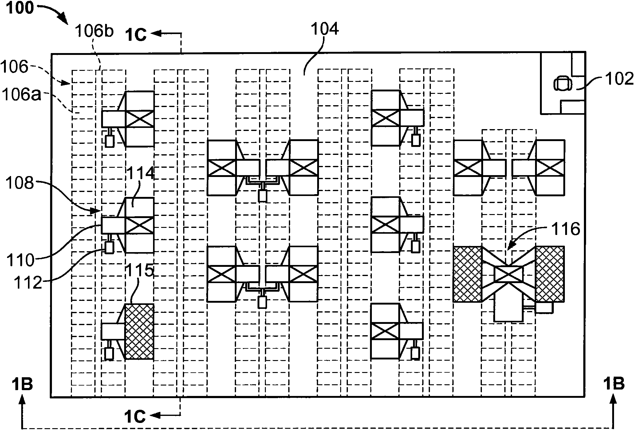
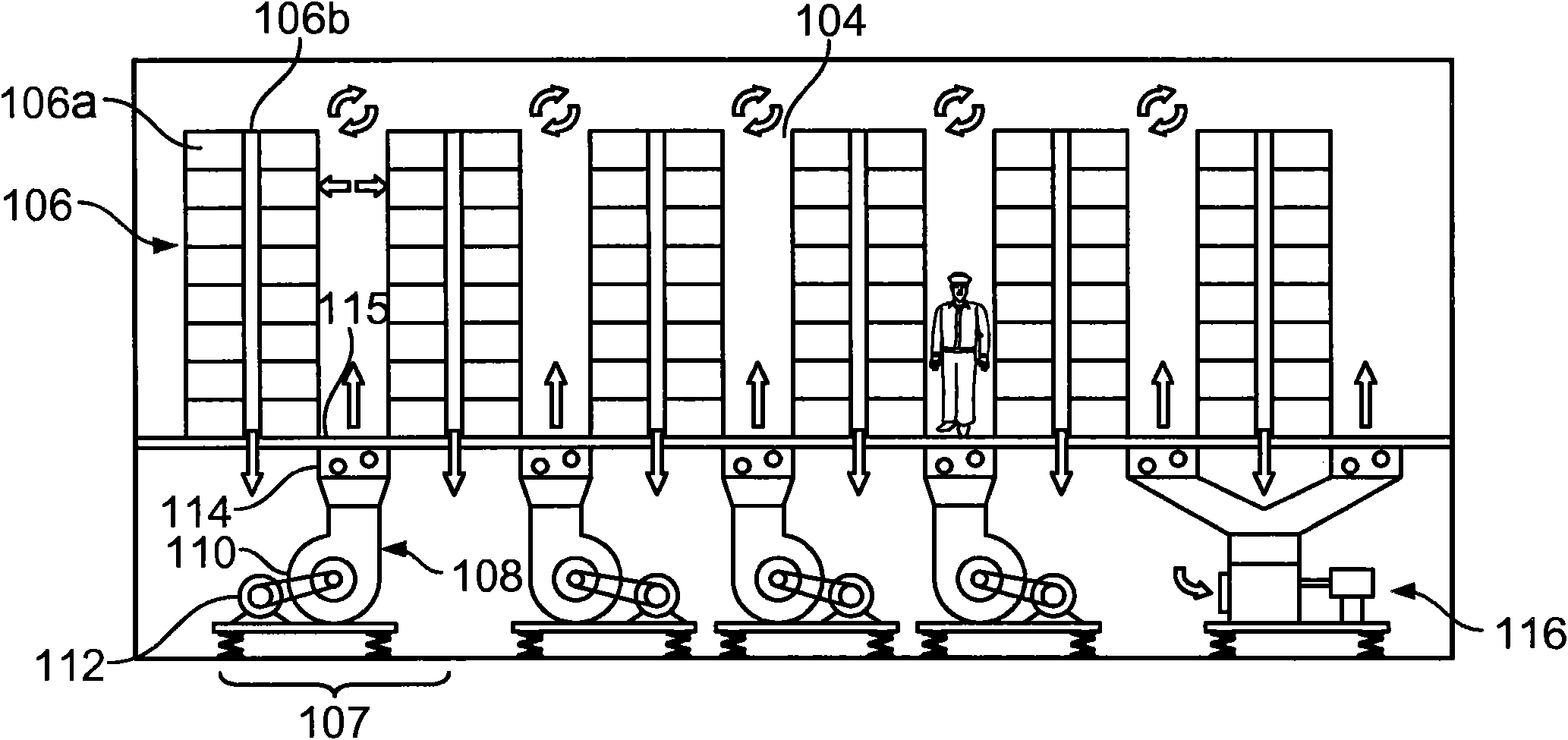
[0036] Figure Ia shows a plan view of the air circulation layout of data center 100, while Figure Ib shows a front cross-sectional view of data center 100 in Figure Ia. Typically, the system shown here provides multiple fan-coil unit combinations that can be located under the floor of a standard data center 100 . Data center 100 is shown in this example as a single-story data center in a warehouse-like facility or other facility that is inexpensive and quick to build. The facility may be constructed as a slab-on-grade facility, or may be set up as a two-story facility, where the on-slab components include computers and the under-slab (under-floor) components include various cooling and other machinery equipment, such as pipes. Where facilities are laminated, plumbing and mechanical equipment can be located under a standard raised floor. Electronics for the computer (not shown) may in turn be located above or below the computer, while electronics for the mechanical equipment ...


PUM


Abstract

A data center cooling system includes a floor structure defining a below-floor warm-air plenum and an above-floor cool air plenum, a plurality of above-floor computer assemblies arranged to exhaust warmed air into the warm-air plenum, and one or more fan-coil arrangements to draw air from the warm-air plenum, cool the air, and provide the air to the cool air plenum. The volume of the above-floor cool air plenum and the below-floor warm air plenum may both be substantial so as to minimize changes in temperature from the failure of components in the system.

Description

technical field [0001] This document deals with techniques for cooling areas containing electronic equipment, such as computer service rooms or server racks in computer data centers. Background technique [0002] As consumers using computers increasingly require heavy-duty online applications, the requirements for multi-computer data centers are greatly increasing. A data center is a centralized computing facility containing hundreds, thousands, or even thousands of computers, usually arranged in multiple computer racks. Data centers are central to modern computing and expensive to build and operate. [0003] Expenses for the construction of data centers include land acquisition and standard construction costs for facilities. Additionally, thousands of computers and supporting equipment had to be purchased and installed. Electronics and mechanics are required to power and cool these devices. [0004] Data centers are expensive to operate because of the need for fast comp...

Claims


Application Information

Patent Timeline
Patent Type & Authority Patents(China)
IPC IPC(8): F24F7/10F24F7/06F24F11/02
CPCF25D17/06H05K7/20745F25D2317/0651F25D2317/0661
Inventor 安德鲁·B·卡尔森吉米·克里达拉斯威廉·哈姆伯根
Owner GOOGLE LLC
Why Eureka
Try Eureka