Temperature control type loop heat pipe evaporator assembly

A loop heat pipe and evaporator technology, applied in the field of spacecraft thermal control, can solve the problems of temperature rise of the controlled heat source, drastic temperature change of the condenser, exceeding the index, etc., and achieve enhanced heat transfer coefficient and heat flux density, precise control The effect of heat source temperature and layout is flexible and convenient

Active Publication Date: 2016-08-31
BEIJING RES INST OF SPATIAL MECHANICAL & ELECTRICAL TECH
View PDF4 Cites 15 Cited by
  • Summary
  • Abstract
  • Description
  • Claims
  • Application Information

AI Technical Summary

Problems solved by technology

However, affected by the heat flow outside the space orbit, the temperature of the condenser changes drastically, which causes the temperature of the liquid working fluid entering the evaporator assembly and the temperature of the controlled heat source to fluctuate accordingly
For example, under extremely low temperature conditions, the liquid working medium entering the evaporation unit is supercooled, making the temperature of the controlled heat source lower than the index in the non-working state; and in the initial stage of the controlled heat source, due to the phase change of the supercooled liquid, a certain overcooling is required. Coldness, the liquid in the evaporator unit cannot boil in time, causing the temperature of the controlled heat source to rise rapidly, exceeding the index
That is, when the controlled heat source is not working or at the beginning of work, the temperature control accuracy cannot be effectively guaranteed, which will limit the application of the temperature control loop heat pipe in the field of precise thermal control of spacecraft (such as the temperature control of optical remote sensor CCD devices)

Method used


Image

  • Temperature control type loop heat pipe evaporator assembly
  • Temperature control type loop heat pipe evaporator assembly
  • Temperature control type loop heat pipe evaporator assembly

Examples


Embodiment Construction

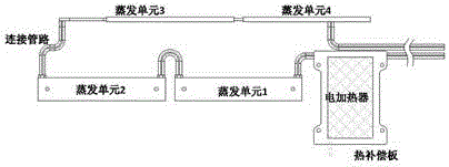
[0022] As a modified product of the traditional loop heat pipe, the temperature-controlled loop heat pipe realizes the separation of the capillary pump and the heat source, and carries heat by designing the evaporator assembly (heat source cold plate assembly) to couple with the heat source. The evaporator assembly consists of multiple evaporating units, which are connected in series / parallel by flexible pipes. The advantages of high temperature accuracy. This makes the advantages of the loop heat pipe more prominent when it is applied to the precise temperature control of the distributed heat source of the spacecraft.

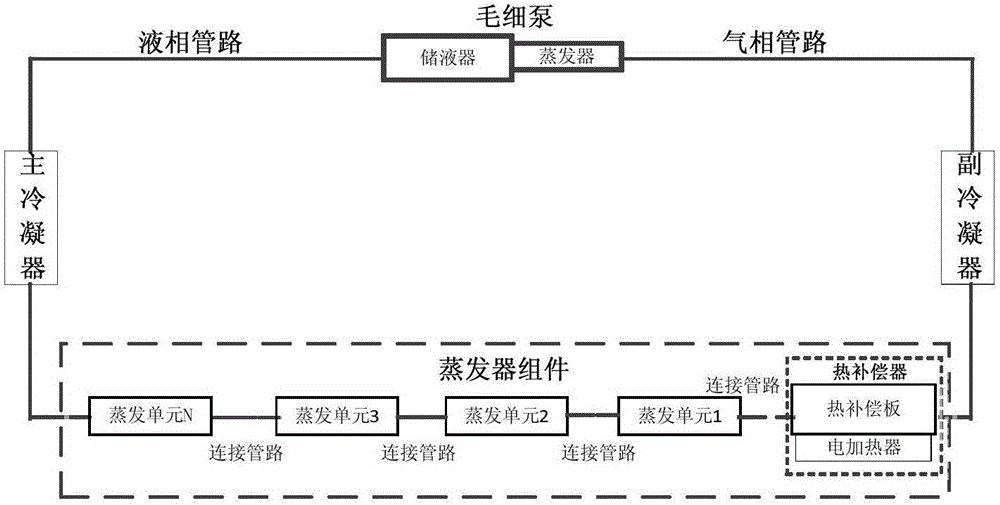
[0023] Such as figure 1 As shown, the temperature-controlled loop heat pipe is mainly composed of a capillary pump, an auxiliary condenser, an evaporator assembly, a main condenser, a gas phase pipeline, and a liquid phase pipeline. When the surface of the capillary core (the right end of the capillary pump) in the capillary pump is heated, the liquid in the...


PUM


Abstract

A temperature control type loop heat pipe evaporator assembly comprises a heat compensator, N evaporation units and a connecting pipeline, wherein the N is a positive integer bigger than or equal to 1; the heat compensator is arranged in the input end so as to heat up the liquid working medium in the loop heat pipe into gas-liquid two-phase state; the N evaporation units are connected by the connecting pipeline so as to form an evaporation network; the input end of the evaporation network is connected with the output end of the heat compensator through the connecting pipeline; the output end of the evaporation network serves as the output end of the evaporator assembly. The evaporator assembly can ensure the working medium entering each evaporation unit in the loop heat pipe operation to be two-phase working medium, thus ensuring constant and consistent temperature of the heat source in working/non working state, and accurately controlling the temperature in the complete cycle.

Description

technical field [0001] The invention belongs to the technical field of spacecraft thermal control, and relates to an evaporator assembly used for a loop heat pipe. Background technique [0002] The loop heat pipe is a two-phase fluid circuit system that uses capillary force to drive the circulation of the working fluid to transfer heat. It has the advantages of small thermal resistance, large heat transfer, long heat transfer distance, and no moving parts. It has been a popular aerospace technology in recent years. One of the high-efficiency thermal control products of the device. [0003] Generally, thermal radiation panels are used as loop heat pipe condensers in spacecraft thermal control systems. However, affected by the heat flow outside the space orbit, the temperature of the condenser changes drastically, which causes the temperature of the liquid working fluid entering the evaporator assembly and the temperature of the controlled heat source to fluctuate accordingly...

Claims


Application Information

Patent Timeline
Patent Type & Authority Applications(China)
IPC IPC(8): F28D15/04F28D15/06
CPCF28D15/043F28D15/06F28D15/0266
Inventor 罗世魁李春林杨涛赵石磊高腾宋欣阳孟庆亮
Owner BEIJING RES INST OF SPATIAL MECHANICAL & ELECTRICAL TECH
Why Eureka
Try Eureka