Drilling rig with mechanical positioning device

A mechanical positioning and drilling rig technology, applied in automatic control devices, metal processing mechanical parts, boring/drilling, etc., can solve the problems of inconvenient access, heavy block gauge, etc., to improve service life, good cooling effect, The effect of improving processing efficiency

Active Publication Date: 2017-05-17
ZHEJIANG XINXING TOOLS CO LTD
View PDF9 Cites 0 Cited by
  • Summary
  • Abstract
  • Description
  • Claims
  • Application Information

AI Technical Summary

Problems solved by technology

If the size of the workpiece is large, the block gauge also needs a large size, resulting in a large weight of the block gauge, which is inconvenient for the operator to take

Method used


Image

  • Drilling rig with mechanical positioning device
  • Drilling rig with mechanical positioning device
  • Drilling rig with mechanical positioning device

Examples


Embodiment Construction

[0037] The present invention will be further described below with reference to the drawings and specific embodiments.

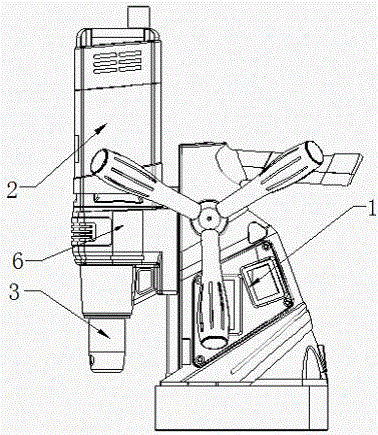
[0038] See attached picture. The drilling rig provided in this embodiment includes a fixed body 1 and a machine head 2 that is perpendicular to the bottom of the machine body to move relatively back and forth, and a spindle 3 for installing tools is provided on the machine head.

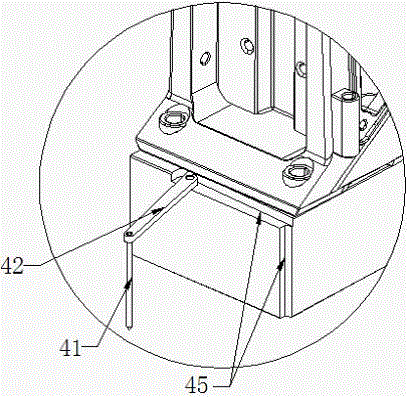
[0039] In order to accomplish the positioning operation conveniently and quickly during the drilling process, the drilling rig of this embodiment is equipped with a mechanical positioning device with a movement limit position. The mechanical positioning device includes a positioning pin 41, and the mechanical positioning device moves to the limit position. At this time, the longitudinal center line of the positioning pin 41 is on the same straight line with the spindle axis.

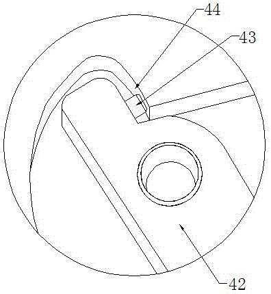
[0040] In the first embodiment, the mechanical positioning device further includes a support rod 42, one end of t...


PUM


Abstract

The invention discloses a drilling machine provided with a mechanical positioning device. The drilling machine comprises a fixed machine body and a machine head which is perpendicular to the bottom of the machine body and moves back and forth relative to the machine body. The machine head is provided with a main shaft provided with a cutter. The drilling machine is further provided with the mechanical positioning device which has a motion limit position, the mechanical positioning device is provided with a positioning needle, and when the mechanical positioning device moves to a limit position, the center line of the length direction of the positioning needle and the axis of the main shaft are on the same line. By means of the drilling machine, positioning of drilling can be conveniently and quickly finished by means of the mechanical positioning device.

Description

Technical field [0001] The invention relates to a mechanical processing equipment, in particular to a drilling rig with a mechanical positioning device. Background technique [0002] When using a traditional drilling machine for drilling, in order to determine whether the center of the tool is the center of the workpiece, it is usually necessary to mark the center line of the hole at the position to be processed on the surface of the workpiece, and punch a center-like punch. Draw the circumference of the hole according to the size of the hole. When drilling, first align the drill bit to the center of the punching hole to drill a shallow pit, and observe whether the shallow pit is concentric with the scribe circle. After it is accurate, continue to complete the drilling. If the shallow pit deviates from the center of the scribe circle, the workpiece needs to be moved to align the two. If the deviation is large, the eye needs to be re-drilled. This kind of drilling positioning me...

Claims


Application Information

Patent Timeline
Patent Type & Authority Patents(China)
IPC IPC(8): B23B39/00B23B47/00B23B19/02B23Q11/10
CPCB23B39/00B23B47/34B23Q1/70B23Q11/1015B23Q15/22
Inventor 姚红飞林敏杰
Owner ZHEJIANG XINXING TOOLS CO LTD
Why Eureka
Try Eureka