Drilling machine with optical positioning device

A technology of optical positioning and drilling rigs, which is applied in the direction of automatic control devices, boring/drilling, large fixed members, etc., can solve the problems of inconvenient access, heavy weight of block gauges, etc., to improve service life, improve processing efficiency, cooling better effect

Active Publication Date: 2014-12-17
ZHEJIANG XINXING TOOLS CO LTD
View PDF10 Cites 4 Cited by
  • Summary
  • Abstract
  • Description
  • Claims
  • Application Information

AI Technical Summary

Problems solved by technology

If the size of the workpiece is large, the block gauge also needs a large size, resulting in a large weight of the block gauge, which is inconvenient for the operator to take

Method used


Image

  • Drilling machine with optical positioning device
  • Drilling machine with optical positioning device
  • Drilling machine with optical positioning device

Examples


Embodiment Construction

[0031] The present invention will be further described below in conjunction with the accompanying drawings and specific embodiments.

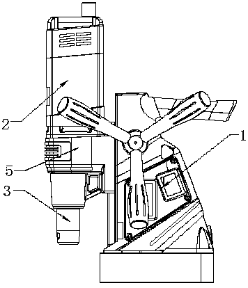
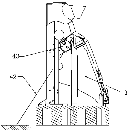
[0032] See attached picture. The drilling rig provided in this embodiment includes a fixed fuselage 1 and a machine head 2 that moves back and forth relative to the bottom of the fuselage. The machine head is provided with a main shaft 3 for installing a cutter.

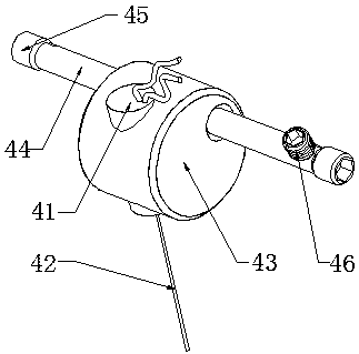
[0033]In the embodiment of the present invention, an optical positioning device is provided on the fuselage 1, and the optical positioning device includes an optical positioning lamp 41, a lamp holder 43 and a shaft 44. In order to enable the optical positioning device to realize the positioning function, the optical positioning lamp 41 emits The intersection point of the light beam 42 and the bottom plane of the fuselage is on the axis of the main shaft 3 . The optical positioning lamp 41 is fixedly installed on the lamp holder 43, and the lamp holder 43 is fixedly installed on the ...


PUM


Abstract

The invention discloses a drilling machine with an optical positioning device. The drilling machine comprises a fixed machine body and a machine head, the machine head moves back and forth by being perpendicular to the bottom of the machine body, and the machine head is provided with a spindle where a tool is installed. The drilling machine further comprises the optical positioning device. The optical positioning device comprises an optical positioning lamp, and the intersection point between light beams emitted by the optical positioning lamp in a power-on state and the bottom plane of the machine body is located on the axis of the spindle. The drilling machine can finish drilling positioning operation conveniently and rapidly.

Description

technical field [0001] The invention relates to a mechanical processing equipment, in particular to a drilling machine with an optical positioning device. Background technique [0002] When using a traditional drilling machine for drilling, in order to determine whether the center position of the tool is the center position of the workpiece to be processed, it is usually necessary to draw the center line of the hole at the position to be processed on the surface of the workpiece, and punch a center-like punch, and then Draw the circumference of the hole according to the size of the hole. When drilling, first align the drill bit with the center of the punching hole to drill a shallow pit, and observe whether the shallow pit is concentric with the marking circle, and continue to complete the drilling after it is accurate. If the shallow pit deviates from the center of the marking circle, it is necessary to move the workpiece to align the two. If the deviation is large, it is ...

Claims


Application Information

Patent Timeline
Patent Type & Authority Applications(China)
IPC IPC(8): B23B39/00B23B47/00B23B19/02
CPCB23B39/00B23Q1/70B23Q15/22
Inventor 郁其娟林敏杰
Owner ZHEJIANG XINXING TOOLS CO LTD
Why Eureka
Try Eureka