
Steel tube multi-angle welding fixture

A welding fixture, multi-angle technology, applied in welding equipment, auxiliary welding equipment, welding/cutting auxiliary equipment, etc., can solve the problem of difficult control of docking

Inactive Publication Date: 2014-12-17
常州聚美精密工具有限公司
View PDF0 Cites 3 Cited by
  • Summary
  • Abstract
  • Description
  • Claims
  • Application Information

AI Technical Summary

Problems solved by technology

But for the welding of steel pipes with curved or inclined joints, it is difficult to control the butt joint of the joints of two steel pipes to be welded

Method used


Image

  • Steel tube multi-angle welding fixture
  • Steel tube multi-angle welding fixture

Examples


Embodiment Construction

[0012] The present invention will be further described below in conjunction with the accompanying drawings and specific embodiments.

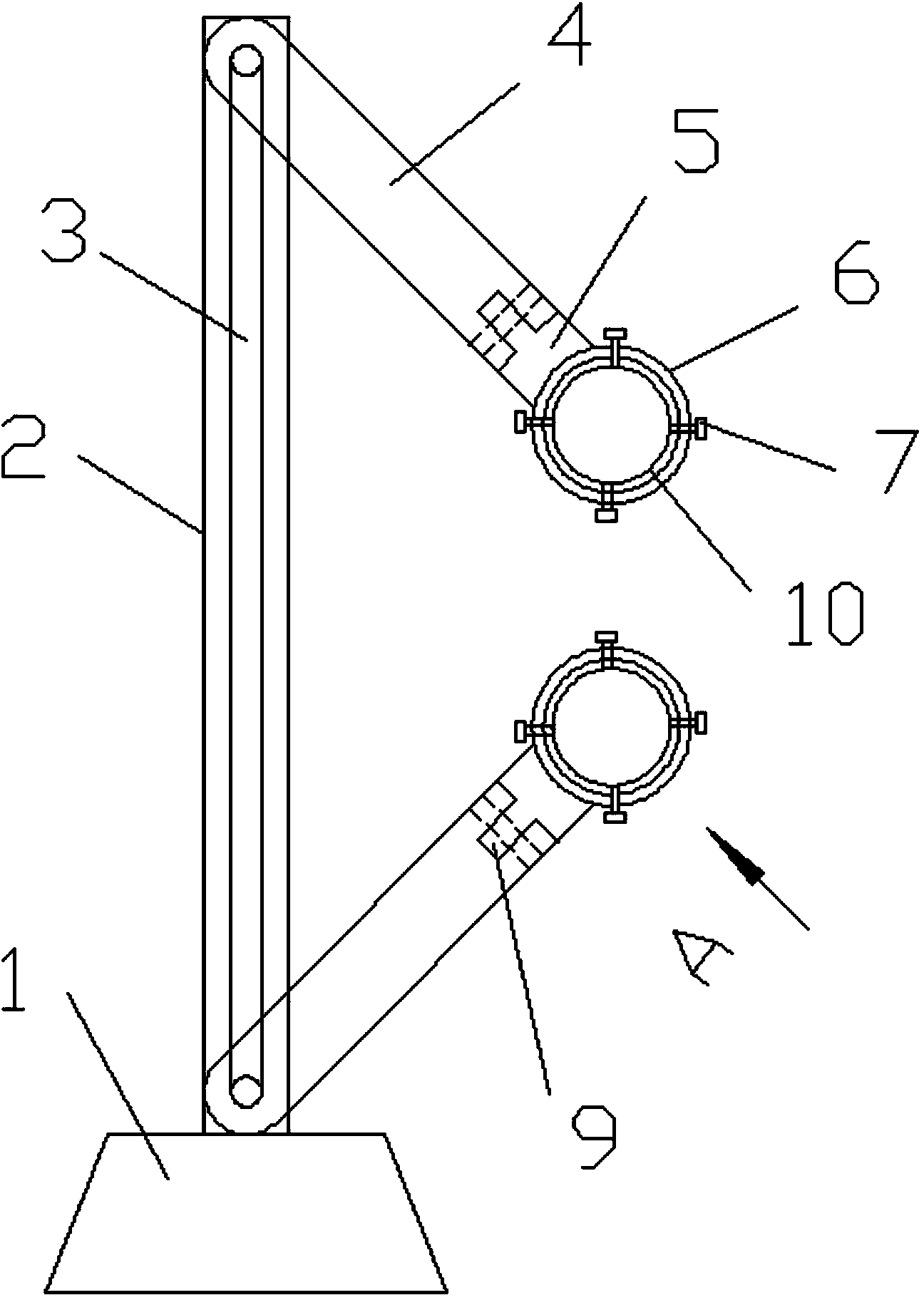
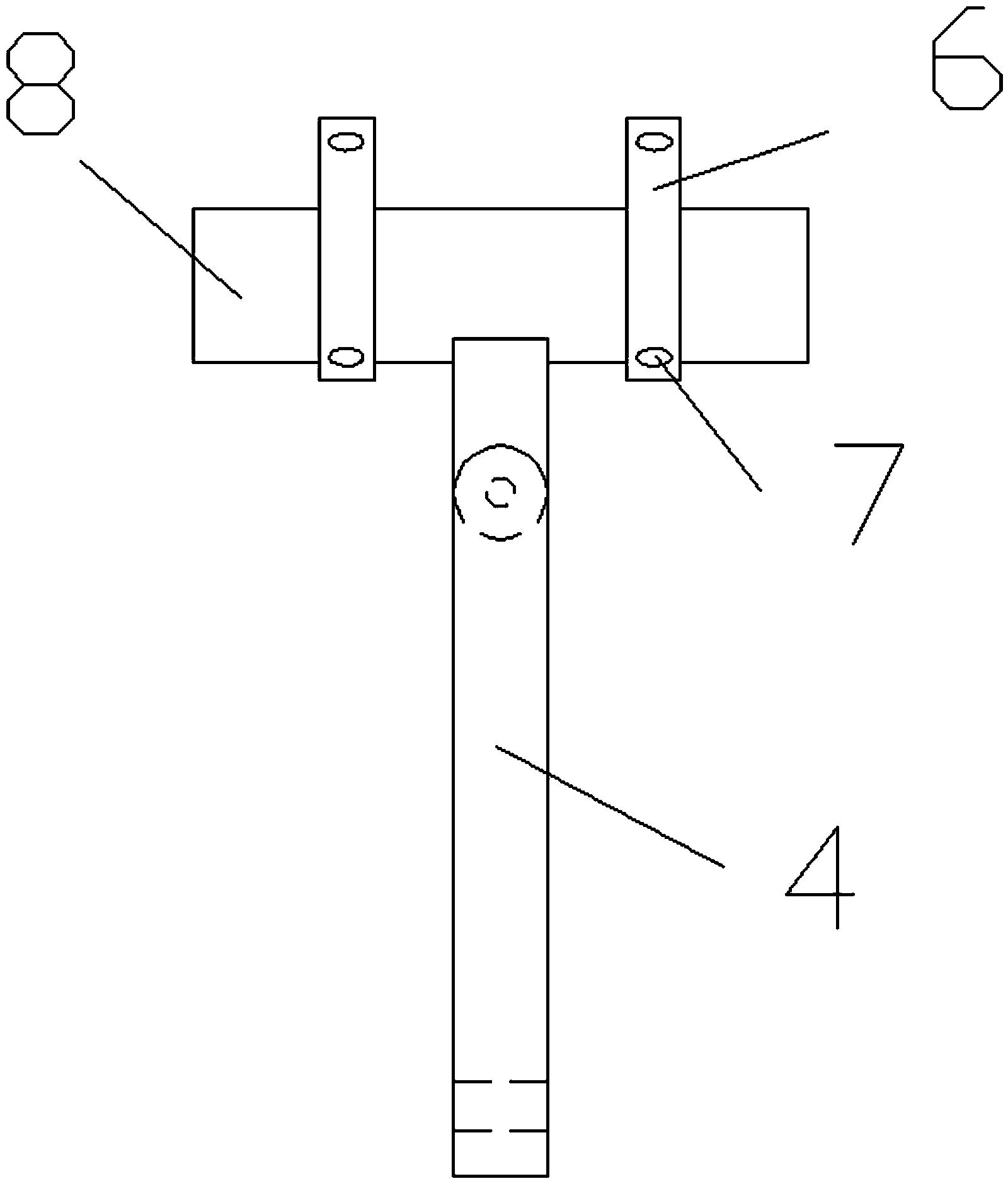
[0013] see figure 1 , 2 , a steel pipe multi-angle welding fixture, including a fixed seat, a column vertically arranged on the fixed seat, a movable arm is movably connected above and below the column, and the movable arm rotates in the plane where the column and the movable arm are located, and the movable arm The end of the arm is provided with a rotating groove 9, and a rotatable steel pipe clamping frame 5 is movably connected in the rotating groove, and the steel pipe clamping frame rotates in the plane where the movable arm and the steel pipe clamping frame are located. The steel pipe clamping frame includes a steel pipe support 8 and two clamping sleeves 6 fixedly sleeved on the steel pipe support, and four fastening bolts 7 are evenly threaded on the clamping sleeves.

[0014] The steel pipe clamping frame clamps the steel pipe 10. W...


PUM


Abstract

The invention relates to a steel tube multi-angle welding fixture. The steel tube multi-angle welding fixture comprises a fixed base and an upright column vertically arranged on the fixed base, wherein the upper side and the lower side of the upright column are respectively and movably connected with a movable arm; each movable arm rotates in the plane where the upright column and the movable arm are located; a rotary slot is arranged on the tail end of each movable arm; a rotational steel tube clamping frame is movably connected to each rotary slot; each steel tube clamping frame rotates in the plane where the corresponding movable arm and the steel tube clamping frame are located. Furthermore, each steel tube clamping frame comprises a steel tube bracket and a plurality of clamping sleeves; a plurality of fastening bolts are uniformly arranged on each clamping sleeve in a penetrating manner. Moreover, a sliding rail for the movable arms to slide up and down is arranged on the upright column. With the adoption of the technical scheme, the steel can rotate in multiple angles through the movable arms and the steel tube clamping frames, the butt joint of joints of steel tubes with bent or inclined joints is realized, and the steel tube multi-angle welding fixture is broader in application range.

Description

technical field [0001] The invention relates to the technical field of welding fixtures, in particular to a steel pipe multi-angle welding fixture. Background technique [0002] For the welding of steel pipes with regular shapes, as long as the interface surfaces of the two steel pipes to be welded are flush and the centerlines of the steel pipes are aligned, in daily life, the welding between the two steel pipes can be realized through a simple welding fixture. But for the welding of steel pipes with curved or inclined joints, the butt joint of the joints of two steel pipes to be welded is difficult to control. Contents of the invention [0003] In view of the above problems, the object of the present invention is to provide a steel pipe multi-angle welding jig. [0004] Realize the technical scheme of the present invention as follows: [0005] The steel pipe multi-angle welding fixture includes a fixed seat and a column vertically arranged on the fixed seat. A movable ...

Claims


Application Information

Patent Timeline
Patent Type & Authority Applications(China)
IPC IPC(8): B23K37/053B23K37/04
CPCB23K37/0533
Inventor 恽益群
Owner 常州聚美精密工具有限公司
Learn More