a mixer truck

A technology of mixer truck and mixing drum, which is applied in cement mixing devices, clay preparation devices, chemical instruments and methods, etc. It can reduce the overturning accident of the reducer, facilitate the installation and positioning, and improve the assembly efficiency.

Active Publication Date: 2016-08-31
SANY AUTOMOBILE MFG CO LTD
View PDF6 Cites 0 Cited by
  • Summary
  • Abstract
  • Description
  • Claims
  • Application Information

AI Technical Summary

Problems solved by technology

However, extremely high precision is required when welding the stopper of the reducer. If the accuracy cannot be guaranteed, the reducer will not be assembled or the gap will be too large, so that it will not be able to limit the position and share the force.
[0005] In the existing industry, the block of the reducer is all welded, and the block of the reducer is basically welded to the top plate of the front desk by the matching welding process. The matching welding can achieve a suitable position accuracy, but the matching welding needs to be carried out in the assembly workshop, which affects Efficiency in assembly, and work such as touch-up painting is required
If the reducer block is pre-welded on the top plate of the front desk, because the shape of the reducer from each manufacturer is not uniform, and the reducer shell is a casting, the accuracy is poor, resulting in poor setting of the position accuracy of the reducer block, often appearing "pre-welding The stopper of the reducer is against the front face of the reducer, and the reducer cannot be assembled", or there is a problem of "there is a gap between the stopper of the reducer and the front end of the reducer, and the stopper does not actually work"
[0006] None of the existing industries has limited the side and upper surface of the reducer, and it is impossible to avoid the displacement of the reducer in the left and right (relative to the symmetrical center of the vehicle frame) and up and down directions (relative to the longitudinal beam wing surface of the vehicle frame) of the mixer truck. The risk of breakage of the reducer mounting bolts cannot be avoided

Method used


Image

  • a mixer truck
  • a mixer truck
  • a mixer truck

Examples


Embodiment Construction

[0031] It should be noted that, in the case of no conflict, the embodiments of the present invention and the features in the embodiments can be combined with each other. The present invention will be described in detail below with reference to the accompanying drawings and examples.

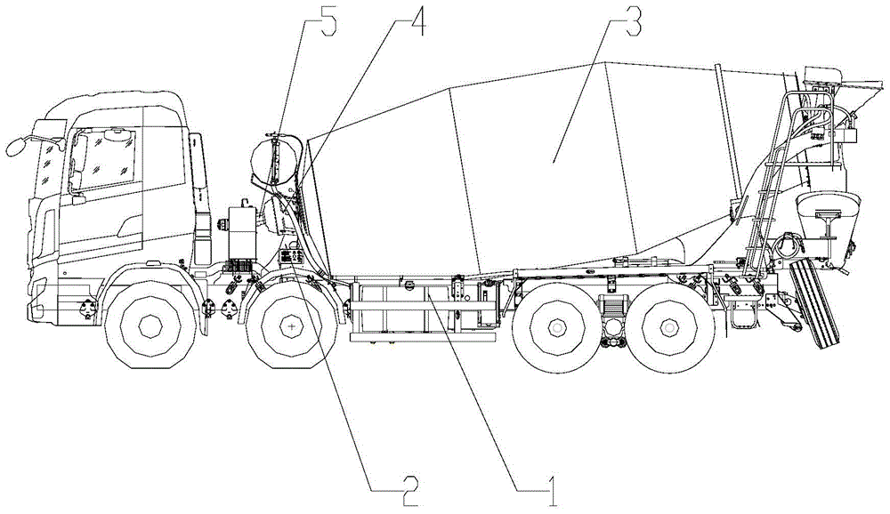
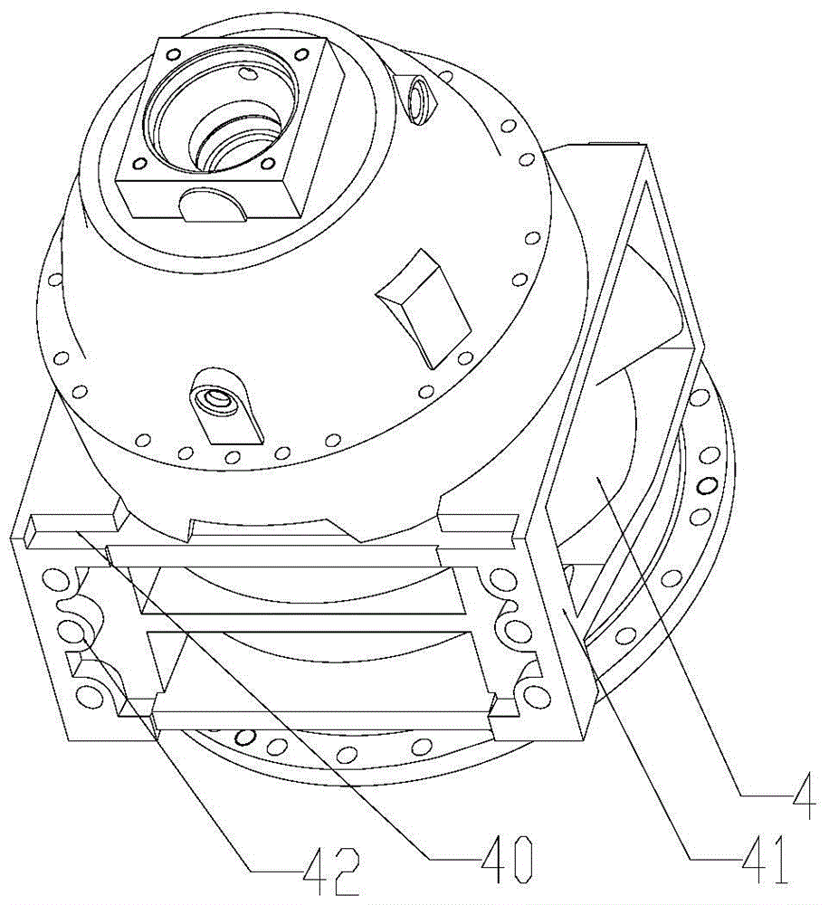
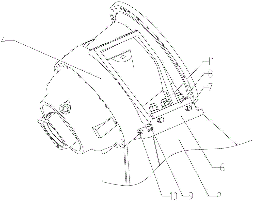
[0032] Such as Figure 1 to Figure 7 Shown, the present invention preferably a kind of mixer truck, comprises chassis 1, is installed with reducer 4, mixing drum 3, hydraulic motor 5 on chassis 1, the container when mixing drum 3 is transported concrete. The speed reducer 4 is an important part of the mixer truck. The speed reducer 4 slows down the output speed of the hydraulic motor 5 in the hydraulic system, increases the torque and transmits it to the mixing drum 3 . The front desk 2 is a part of the auxiliary frame on the mixer truck chassis, the front desk top plate 6 is installed on the front desk 2, and the speed reducer 4 is installed on the front desk top plate 6; two rows of six bolt h...


PUM


Abstract

The invention discloses a mixer truck, which comprises a speed reducer, a mixing drum and a hydraulic motor, and the speed reducer is respectively connected with the mixing drum and the hydraulic motor. It also includes the front desk, the front top plate, the front baffle, the side baffle, the first adjustment bolt, and the second adjustment bolt; the front top plate is installed on the front desk, and the reducer is installed on the front desk top plate; and the side boss, the front baffle is located between the front boss and the reducer, the first adjusting bolt presses the front baffle; the side baffle is located between the side boss and the reducer, and the second adjusting bolt presses the side baffle . The present invention limits and protects the front, left and right sides, and up and down directions of the reducer through the front baffle and side baffles, so as to avoid the risk of breakage of the installation bolts of the reducer.

Description

technical field [0001] The invention relates to the field of engineering machinery, in particular to a mixer truck. Background technique [0002] Concrete mixer truck (hereinafter referred to as mixer truck) is a special vehicle for mixing and transporting concrete, which is composed of a car chassis and a special device for concrete mixing and transportation (mixing drum, etc.). [0003] The reducer is an important part of the mixer truck. The reducer is used to decelerate the output speed of the motor in the hydraulic system, increase the torque and transmit it to the mixing drum (container when transporting concrete). [0004] The front desk is a part of the auxiliary frame of the mixer truck. The reducer is installed on the top plate of the front desk. The front baffle of the reducer is set at the front end of the front desk. Part of the impact. However, extremely high precision is required when welding the stopper of the reducer. If the accuracy cannot be guaranteed, ...

Claims


Application Information

Patent Timeline
Patent Type & Authority Patents(China)
IPC IPC(8): B28C5/42
CPCB28C5/42
Inventor 温春明张克军任玉晓
Owner SANY AUTOMOBILE MFG CO LTD
Why Eureka
Try Eureka