Underground diaphragm wall bottom reinforcing structure and construction method thereof

A technology of underground diaphragm wall and reinforcement structure, which is applied in basic structure engineering, sheet pile wall, building and other directions, can solve the problems of high cost, large supporting cost of water-stop curtain, settlement and deformation of surrounding buildings or foundation subsidence, etc. Achieve the effect of low cost, ensure the safety of foundation pit support, and restrain the problem of uneven settlement

Pending Publication Date: 2019-05-07
BEIJING FOURTH CONSTR & ENG +1
View PDF0 Cites 2 Cited by
  • Summary
  • Abstract
  • Description
  • Claims
  • Application Information

AI Technical Summary

Problems solved by technology

[0006] The purpose of the present invention is to provide a reinforcement structure for the bottom of an underground diaphragm wall and its construction method. To solve the problem of using a large number of dewatering equipment for root support of an underground diaphragm wall in an area rich in groundwater, the cost is huge, the surrounding environment is greatly affected, and the surrounding buildings or The technical problem of subsidence, settlement and deformation of the foundation has to be solved, and it is necessary to solve the technical problem of setting up a separate water-stop curtain that requires a lot of extra support costs

Method used


Image

  • Underground diaphragm wall bottom reinforcing structure and construction method thereof
  • Underground diaphragm wall bottom reinforcing structure and construction method thereof
  • Underground diaphragm wall bottom reinforcing structure and construction method thereof

Examples


Embodiment Construction

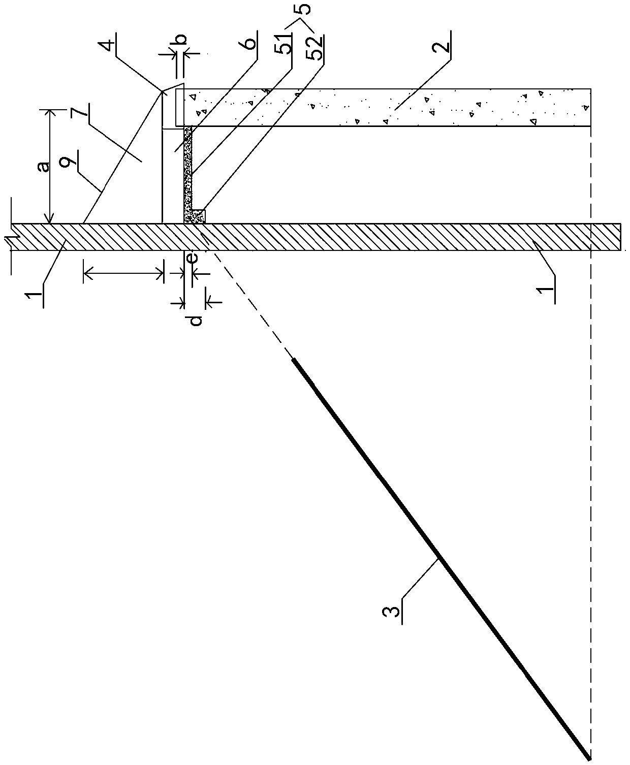
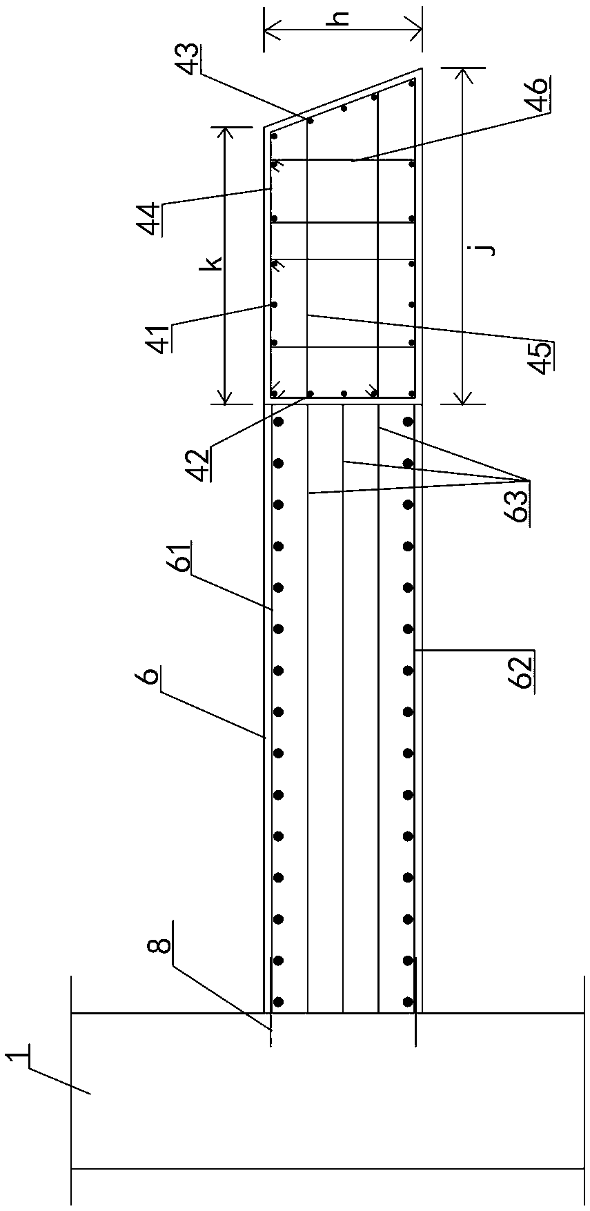
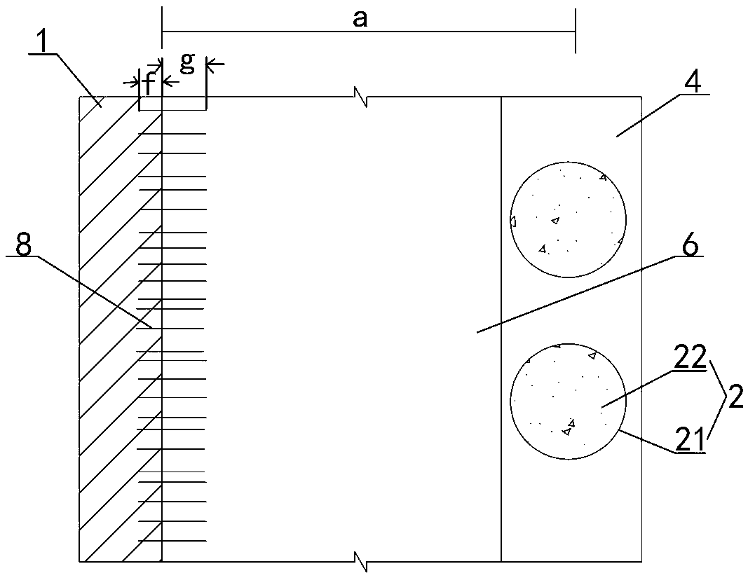
[0052] Examples see Figure 1-4 As shown, a reinforcement structure for the bottom of an underground diaphragm wall includes an underground diaphragm wall 1, and also includes a row of bored piles 2 driven into a row at a distance between the bottom inner side of the underground diaphragm wall and the underground diaphragm wall. The specific reinforcement length It is determined according to the precipitation and the surrounding environment, so as to ensure that the connecting wall covers the part where the anchor cable cannot be laid. The distance between the underground diaphragm wall 1 and the bored pile 2 is a=3m-5m. The lower surface of the bored cast-in-place pile is flush with the bottom end of the bottom row of the underground diaphragm wall where the anchor cables 3 cannot be laid, and the top of the bored cast-in-place pile is connected as a whole by a crown beam 4 . The bored cast-in-place pile 2 is a steel pipe concrete pile, and the thickness b of the top of the ...


PUM


Abstract

The invention provides an underground diaphragm wall bottom reinforcing structure and a construction method thereof. The reinforcing structure comprises an underground diaphragm wall and bored piles,wherein the lower side surfaces of the bored piles are flush with the bottom end of the very bottom, not capable of being provided with anchor cables, of the underground diaphragm wall, the pile topsof the bored piles are integrally connected with one another through a crown beam, a connecting plate cushion and an anti-side force connecting plate are fixedly connected between the bored piles andthe underground diaphragm wall, the upper side surfaces of the anti-side force connecting plate and crown beam are fixedly connected with a slope type back pressure concrete block, the side cross section of the slope type back pressure concrete block is a right triangle, and slope surface inclines from the outside to the inside to form a drainage face. The underground diaphragm wall bottom reinforcing structure and the construction method thereof have the advantages that the design concept of underground diaphragm wall bottom stress equivalent equal-strength substitution is adopted, the forcetransmission path is reasonable, the safety of foundation supporting is ensured, the corner capsizing resistance of the connecting plate close to the underground diaphragm wall is effectively enhanced, the construction is simple, fast and convenient, the surrounding environment is not affected, and the cost is lower.

Description

technical field [0001] The invention relates to a ground connecting wall, in particular to a reinforced ground connecting wall bottom structure and a construction method thereof. Background technique [0002] The underground diaphragm wall is usually reinforced by setting anchor cables. For areas with rich groundwater in coastal areas, difficult precipitation, difficult hole formation, or complex pipelines in the ground, it is usually impossible to perform anchor cable tensioning for hole formation, and conventional reinforcement methods such as anchor cable tensioning at the root of the underground diaphragm wall will cause the bottom of the underground diaphragm wall to There is a risk of overturning in the support, especially it is difficult to carry out the construction work of the last row of anchor cables at the root of the underground diaphragm wall, which brings potential safety hazards. [0003] In view of this situation, the existing technology generally adopts th...

Claims


Application Information

Patent Timeline
Patent Type & Authority Applications(China)
IPC IPC(8): E02D5/00E02D5/34E02D19/00
CPCY02E10/20
Inventor 苑会杰巴盼锋徐汇宾马小军孙忠耿光辉李东华冯培进
Owner BEIJING FOURTH CONSTR & ENG
Why Eureka
Try Eureka