Optical fiber drawing device and drawing method thereof

A wire drawing and optical fiber technology, applied in the field of optical fiber manufacturing, can solve the problems of changing the process gas flow rate and ratio, and achieve the effect of reducing production costs and saving energy consumption

Active Publication Date: 2014-12-17
TONGDING INTERCONNECTION INFORMATION CO LTD
View PDF5 Cites 14 Cited by
  • Summary
  • Abstract
  • Description
  • Claims
  • Application Information

AI Technical Summary

Problems solved by technology

[0004] The total amount of process gas and the proportion of each gas required for various types of preforms in the fiber drawing process are different. The patents that have been published so far are all continuously fed with the process gas at the same flow rate and ratio. There is no patent based on heating The size of the element and the type of the optical fiber preform determine the total amount of process gas required and the ratio of each process gas, and there is no patent to change the process according to the gap between the heating element and the optical fiber preform at each stage of drawing Gas flow and ratio

Method used


Image

  • Optical fiber drawing device and drawing method thereof
  • Optical fiber drawing device and drawing method thereof
  • Optical fiber drawing device and drawing method thereof

Examples


Embodiment 1

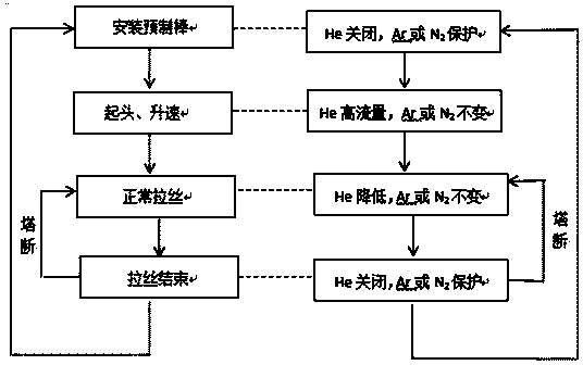
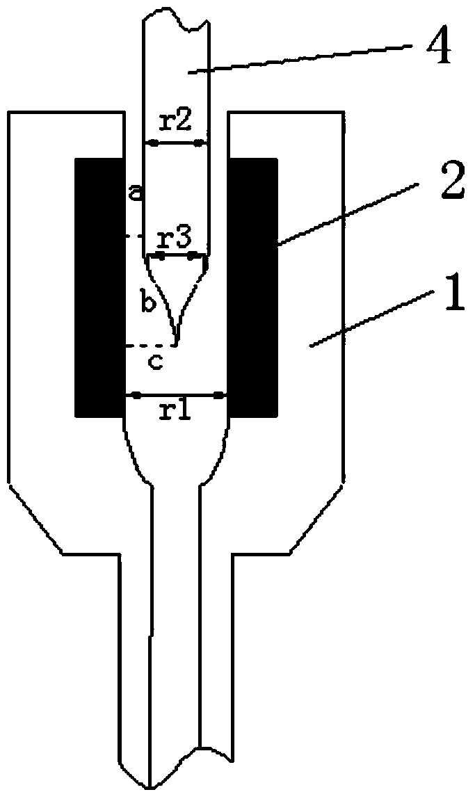
[0040] like Figure 4 As shown, use an optical fiber preform with an outer diameter of 140mm for drawing, and select the inner diameter r of the graphite heating element 1 It is 164mm. In order to ensure the normal drawing stage, the gas flow rate of helium in the fiber forming area is not less than 0.15m / min. According to V=0.15*π*r 1 2 / 4 Calculate the flow rate of helium gas in the inert protective gas into the wire drawing furnace to be 3.2L / min. The wire drawing furnace softens the optical fiber preform, pulls out the optical fiber with the required diameter, cools it through the cooling pipe, and coats the coating with a protective coating. The effectively deposited part of the rod is all drawn into a qualified fiber, and the drawing furnace is closed. During the wire drawing process, when the temperature of the wire drawing furnace is lower than 1500℃, the control device will automatically recognize that this stage is in the furnace shutdown stage, and only pass in a...

Embodiment 2

[0043] like Figure 7 As shown, use an optical fiber preform with an outer diameter of 180mm for drawing, and select the inner diameter r of the graphite heating element 1 It is 216mm. In order to ensure the normal drawing stage, the gas flow rate of helium in the fiber forming area is not less than 0.15m / min. According to V=0.15*π*r 1 2 / 4 Calculate the flow rate of helium gas in the inert protective gas into the wire drawing furnace to be 5.5L / min. During the wire drawing process, when the temperature of the wire drawing furnace is lower than 1500℃, the control device will automatically recognize that this stage is in the furnace shutdown stage, only pass in argon or nitrogen protection, and turn off the helium gas; when the temperature of the wire drawing furnace is greater than 1500℃, and the speed is less than or equal to 1800m / min, the control device automatically recognizes that this stage is in the starting and speed-up stages (including the heating-up U-turn stage,...

Embodiment 3

[0046] like Figure 10 As shown, use an optical fiber preform with an outer diameter of 200mm for drawing, and select the inner diameter r of the graphite heating element 1 It is 226mm. In order to ensure the normal drawing stage, the gas flow rate of helium in the fiber forming area is not less than 0.15m / min. According to V=0.15*π*r 1 2 / 4 Calculate the flow rate of helium gas in the inert protective gas into the wire drawing furnace to be 6L / min. During the wire drawing process, when the temperature of the wire drawing furnace is less than 1500℃, the control device will automatically recognize that this stage is in the furnace shutdown stage, only pass in argon or nitrogen protection, and turn off the helium gas; when the temperature of the wire drawing furnace is greater than 1500℃, and the speed is less than or equal to 2000m / min, the control device automatically recognizes that this stage is in the starting and speed-up stages (including the heating-up U-turn stage, t...


PUM


Abstract

The invention relates to the technical field of optical fiber manufacturing, and particularly relates to an optical fiber drawing device and a drawing method of the fiber drawing device. The optical fiber drawing device comprises a drawing furnace body and a gas control device, wherein a graphite heating element, a heating oil and an inert protective gas channel are arranged inside the furnace body; the gas control device is connected with the inert protective gas channel and controls the gas flow of the inert protective gas channel; a bar hanging platform is arranged above the furnace body; the tail end of an optical fiber preform rod is connected with the bar hanging platform through a quartz glass tail pipe; and a cooling pipe, a coating device, a curing unit and a draft gear are sequentially arranged below the outlet of the furnace body. The helium gas flow for normally drawing is determined according to the inner diameter of a graphite heating element of the drawing furnace; different helium gas flow is set at different process stages; and different process stages are defined according to the technological parameters such as the drawing speed, the drawing furnace temperature and the like, thus the helium gas flow at different process stages is automatically controlled; energy consumption is saved; and the production cost is reduced.

Description

technical field [0001] The invention relates to the technical field of optical fiber manufacturing, in particular to an optical fiber drawing device and a drawing method thereof. Background technique [0002] Optical fiber drawing is the process of heating and softening the optical fiber preform and drawing it into an optical fiber of suitable size and coating it. Since the softening of the optical fiber preform requires a high temperature of 2000 °C, induction furnaces and resistance furnaces are mainly used at present. The heating elements of these two kinds of drawing furnaces are mainly graphite, and the graphite parts are easily oxidized at high temperatures, resulting in the strength of the drawn optical fiber. The problem of deterioration, in order to prevent the oxidation of the graphite heating element, it is necessary to maintain an inert gas atmosphere in the drawing furnace. At present, the commonly adopted method is to introduce a certain amount of argon, nitrog...

Claims


Application Information

Patent Timeline
Patent Type & Authority Applications(China)
IPC IPC(8): C03B37/025
Inventor 沈小平李鑫鑫沈文义朱建友吴仪温范修远
Owner TONGDING INTERCONNECTION INFORMATION CO LTD
Why Eureka
Try Eureka