[0034] The present invention will be described in detail below with reference to the drawings and embodiments.
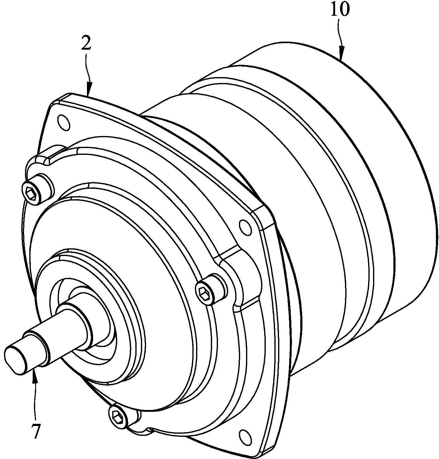
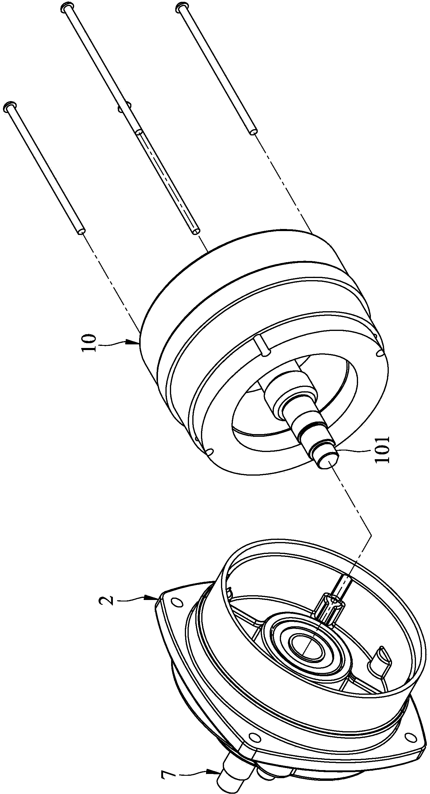
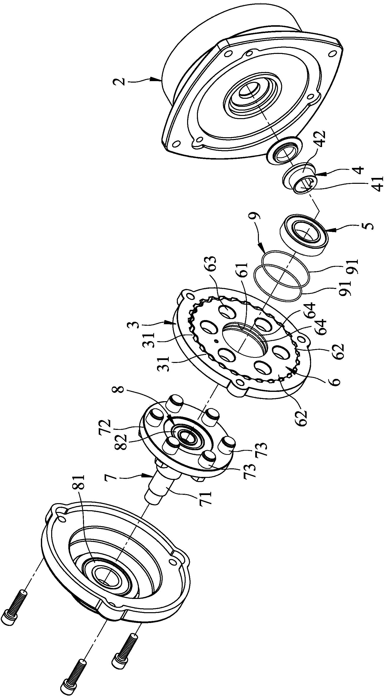
[0035] Such as figure 1 , figure 2 and image 3 As shown, the low-tooth-difference reducer of the present invention that can reduce noise and wear is suitable for connecting an input shaft 101 of a motor 10, and includes a housing base 2, an internal gear 3, an eccentric body 4, and a pivot Piece 5, an external gear 6, an output shaft 7, a pivot unit 8, and a shock-absorbing unit 9.
[0036] Such as image 3 , Figure 4 ,and Figure 5 As shown, the internal gear 3 is disposed on the housing base 2 and is integrally formed, and includes a plurality of internal teeth 31.
[0037] The eccentric body 4 is spaced apart from the internal gear 3 on the input shaft 101, can rotate synchronously with the input shaft 101, and includes an inner ring surface 41 adjacent to the input shaft 101, and an inner ring surface 41 corresponding to the input shaft 101. The shaft 101 is an outer ring 42 eccentrically arranged. In this embodiment, the eccentric body 4 and the input shaft 101 are manufactured separately and then assembled and assembled. Of course, they can also be integrally formed (not shown).
[0038] The pivot member 5 is sleeved on the outer ring surface 42 of the eccentric body 4. In this embodiment, the pivoting member 5 is a ball bearing, which cannot be limited in specific implementation.
[0039] The externally toothed gear 6 is pivotally disposed on the outer ring surface 42 of the eccentric body 4 by the pivoting member 5, and includes a pivoting surface 61 adjacent to the pivoting member 5, and a plurality of pivoting surfaces 61 arranged at intervals , A plurality of inner pin holes 63 arranged in an annular arrangement and spaced between the pivoting surface 61 and the outer teeth 62, and a plurality of first grooves 64 formed on the pivoting surface 61. The externally toothed gear 6 and the internally toothed gear 3 have a slight difference in the number of teeth, and when the input shaft 101 rotates, the eccentric body 4 and the pivoting member 5 constantly maintain at least one external tooth 62 meshing with the internal tooth Gear 3.
[0040] The output shaft 7 is coaxially arranged with the input shaft 101 and spaced apart, and includes a shaft portion 71 protruding outward from the housing 2 and a disk portion connected to the shaft portion 71 and corresponding to the external gear 3 72, and a plurality of inner pins 73 arranged on the disc 72, the inner pins 73 can be inserted into the corresponding inner pin holes 63, and the outer diameter is smaller than the inner diameter of the inner pin holes 63.
[0041] Preferably, the inner pins 73 respectively have an inner pin rod 731 that is kept tightly embedded with the disc portion 72 of the output shaft 7, and a disc portion 72 away from the output shaft 7 is provided with a limiting protrusion on the inner pin rod 731. The edge 732 and an inner roller 733 pivotally sleeved on the inner pin rod 731 and capable of being restricted by the restricting flange 732. In this embodiment, the inner pin 731 respectively has a plurality of second grooves 735 adjacent to the corresponding inner roller 733, and is integrally formed with the limiting flange 732, and is limited by a nut 734 It is locked to the disc 72 of the output shaft 7.
[0042] The pivot unit 8 includes a first pivot member 81 arranged between the housing 2 and the output shaft 7, and a disc 72 embedded in the output shaft 7 and capable of feeding the input shaft 101 Abut the second pivot member 82 that pivots. The second shaft pivot 82 can increase the coaxiality of the input shaft 101 corresponding to the output shaft 7. In this embodiment, the first pivot member 81 and the second pivot member 82 are both ball bearings, which cannot be limited in implementation.
[0043] The shock-absorbing unit 9 includes a plurality of external gear shock-absorbing members 91 and a plurality of inner roller shock-absorbing members 92. In this embodiment, the external gear shock-absorbing member 91 and the inner-roller shock-absorbing member 92 are O-rings, and can also be made of other materials with elastic buffering ability in specific implementation.
[0044] The external gear shock-absorbing member 91 is respectively located between the pivoting surface 61 of the external gear 6 and the pivoting member 5, and is embedded in the first groove 64. Of course, the low-tooth-difference reducer capable of reducing noise and wear of the present invention can also include only one external gear shock-absorbing member 91, and the external gear 6 can also include only one second gear that can accommodate the external gear shock-absorbing member 91. A groove 64. At this time, the external gear shock-absorbing member 91 can be a washer with a larger contact area (not shown).
[0045] The inner roller shock-absorbing member 92 is respectively accommodated between the inner pin rod 731 and the corresponding inner roller 733, and is embedded in the second groove 735. It is worth noting that each inner pin rod 731 can also have only one second groove 735 that can accommodate the corresponding inner roller shock-absorbing member 92. At this time, the inner roller shock-absorbing member 92 can be in contact with each other. Larger washer (not shown).
[0046] Such as image 3 , Figure 5 ,and Image 6 As shown, in this embodiment, the internal teeth 31 of the internal gear 3 are in a circular-arc tooth profile, and the external teeth 61 of the external gear 6 are in a cycloid tooth profile ( trochoidal tooth profile). Of course, the tooth shapes of the inner teeth 31 and the outer teeth 61 can also be exchanged. When the difference between the number of the internal teeth 31 of the internal gear 3 and the number of the external teeth 61 of the external gear 6 is 1, the rotation speed of the input shaft 101 is reduced to 1/ of the external gear 6 The number of teeth is transmitted to the inner pin 73 of the output shaft 7 through the inner pin hole 63 when the external gear 6 is eccentrically rotated, thereby driving the output shaft 7 to decelerate and pivot.
[0047] In addition, the internally toothed gear 3 and the externally toothed gear 6 are made of powder metallurgy, and there is no need to perform ultra-high-precision processing for the internally toothed gear 3 and the externally toothed gear 6 after the production is completed. The concentricity derived at this time Tolerance issues can be further achieved by arranging the external gear shock-absorbing member 91 to absorb the dimensional tolerance between the internal gear 3 and the external gear 6 when they are meshing and rotating; it can also be passed through the inner roller shock-absorbing member 92. Absorb the vibration caused by the dimensional tolerance when the external gear 6 is transmitted to the output shaft 7, thereby not only achieving the advantage of allowing a larger tolerance value, but also reducing the vibration caused by the internal gear 3 and the external gear. The gear 6 and the output shaft 7 are all rigid bodies, which cause noise and wear problems.
[0048] The internally toothed gear 3 and the externally toothed gear 6 can also be produced by using mold casting or the like which has a lower cost than powder metallurgy, but this should not be the limit. It is worth mentioning that in this embodiment, only one of the external gear shock-absorbing member 91 and the inner roller shock-absorbing member 92 can be separately provided, so as to still achieve the effect of reducing noise and wear, so it cannot be used This is limited.
[0049] Through the above structure, the advantages and effects of the reducer with small tooth difference that can reduce noise and wear can be summarized as follows:
[0050] 1. The internally toothed gear 3 and the externally toothed gear 6 do not need to be processed with ultra-high precision after being processed and formed, so the cost required for manufacturing can be greatly reduced.
[0051] 2. By providing the external gear shock-absorbing member 91 and the inner roller shock-absorbing member 92, the internal gear 3 and the external gear 6 can be allowed to have a larger tolerance value, and the internal gear 3 and the internal gear can be reduced. The external gear 6 is a rigid body, which causes noise and wear problems.
[0052] 3. By providing the first pivot member 81, the output shaft 7 can be firmly pivoted on the housing base 2, and then by providing the second pivot member 82, in addition to improving the input shaft 101 relative to The concentricity of the output shaft 7 can also reduce the volume of the preferred embodiment, and can be installed in a narrower space.
[0053] Combining the above advantages and effects, it can indeed achieve the purpose of the invention.