Reflecting display panel, manufacture method thereof and display device

A reflective display and display panel technology, applied in nonlinear optics, instruments, optics, etc., can solve the problem of low display brightness, and achieve the effect of improving display brightness and utilization rate

Inactive Publication Date: 2014-12-17
BOE TECH GRP CO LTD
View PDF9 Cites 13 Cited by
  • Summary
  • Abstract
  • Description
  • Claims
  • Application Information

AI Technical Summary

Problems solved by technology

[0002] Reflective display devices in the prior art generally add polarizers on the top and bottom of the display panel or at least add polarizers on one side of the display panel and cooperate with a com

Method used


Image

  • Reflecting display panel, manufacture method thereof and display device
  • Reflecting display panel, manufacture method thereof and display device
  • Reflecting display panel, manufacture method thereof and display device

Examples


Embodiment 1

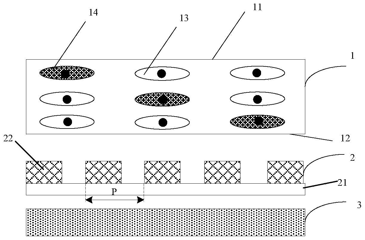
[0032] The present invention provides a reflective display panel, such as figure 1 and figure 2 As shown, the method includes:

[0033] A guest-host liquid crystal cell 1, the guest-host liquid crystal cell includes an upper substrate 11, a lower substrate 12, and liquid crystal molecules 13 and dichroic dye molecules 14 encapsulated between the upper and lower substrates, the liquid crystal molecules 13 and the dichroic dye molecules 14 constitute a guest-host liquid crystal layer; Wherein the upper surface of the upper substrate is used as an incident surface of ambient light, that is, the upper surface of the upper substrate faces the viewer.

[0034] A wire grid polarizer 2 (Wire grid polarizer, WGP) is arranged below the guest-host liquid crystal cell 1, and the wire grid polarizer 2 includes a substrate 21 and strip-shaped protrusions 22 on the substrate 21, and the liquid crystal molecules 13 The arrangement direction is the same as the extending direction of the str...

Embodiment 2

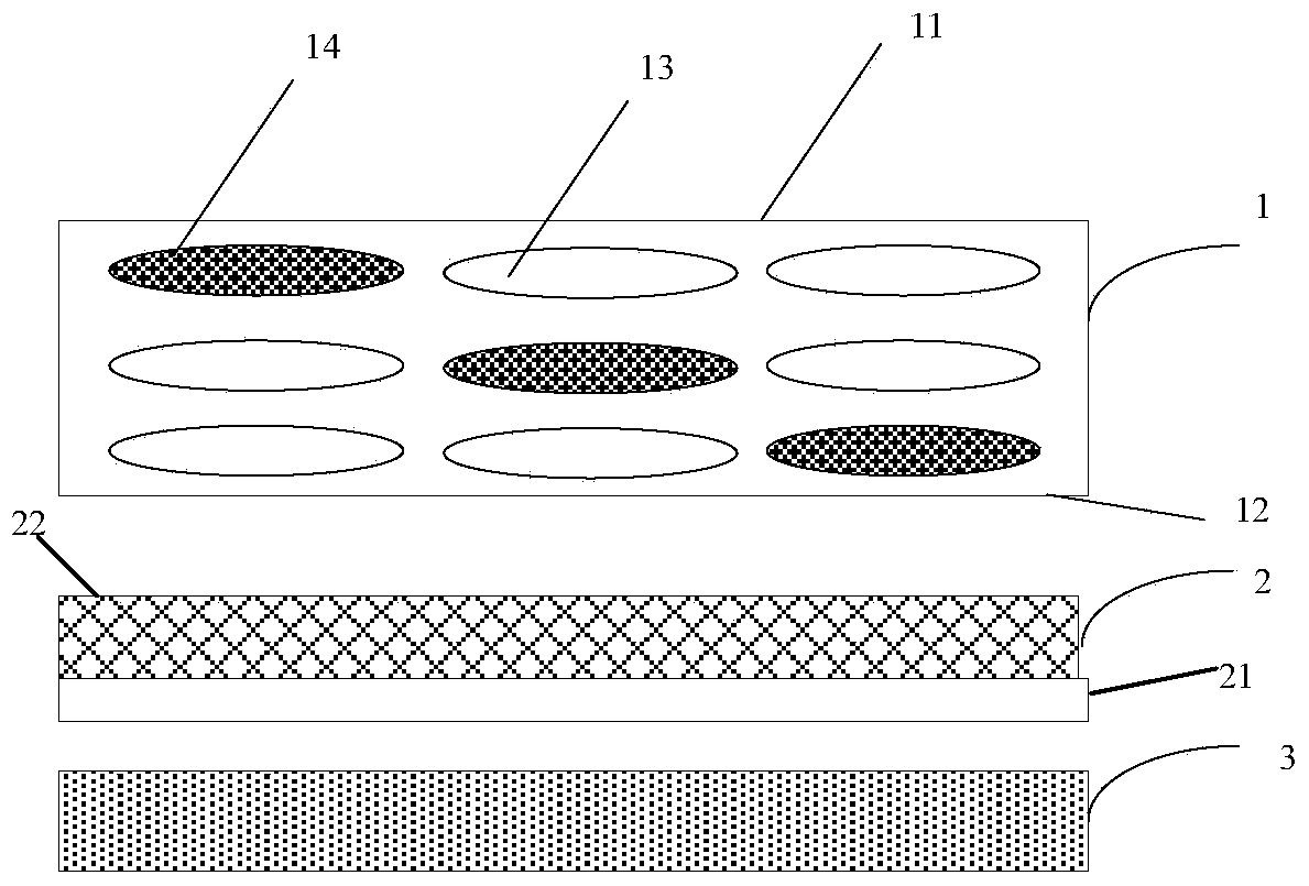
[0043] The difference from the reflective display panel provided in Embodiment 1 is that, as Figure 4 As shown, in the second embodiment of the present invention, the strip-shaped protrusions 22 constituting the wire grid polarizing layer are formed on the upper surface of the lower substrate 12 of the guest-host liquid crystal cell 1 . At this time, there is no need to specially arrange a substrate for carrying the wire grid polarizing layer, further reducing the thickness of the entire display panel.

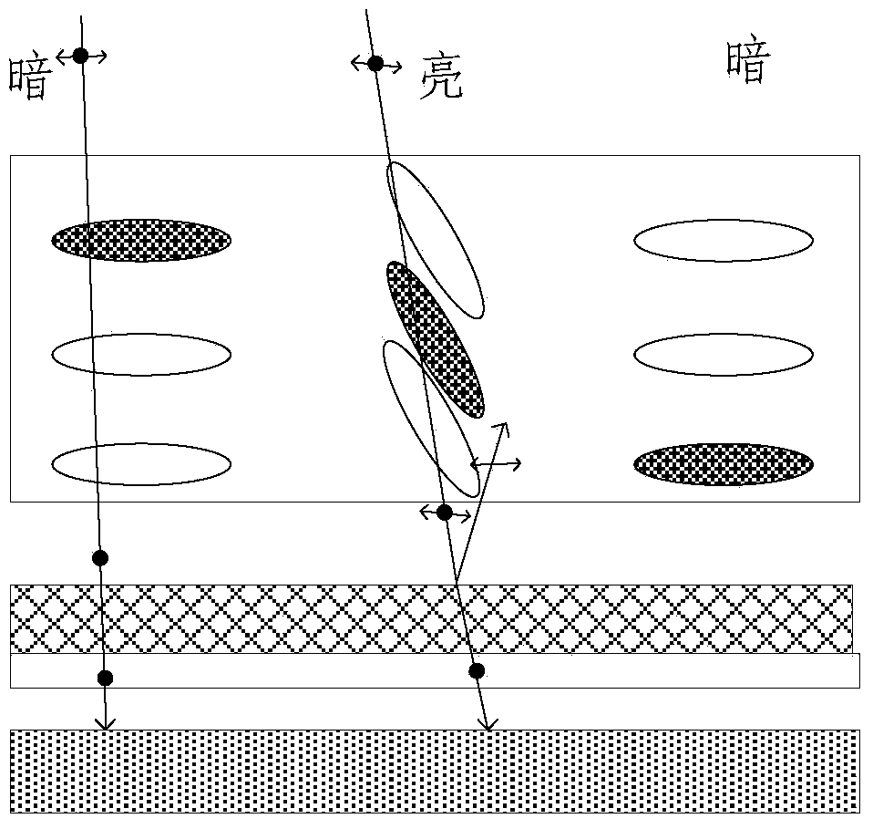
[0044]The working principle of the reflective display panel provided in the second embodiment is the same as that of the reflective display panel in the first embodiment, and will not be described in detail here.

[0045] It should be pointed out that although Embodiment 1 or 2 shows the situation that the wire grid polarizing layer is located on the upper surface of the corresponding substrate, in practical applications, the wire grid polarizing layer may also be located on ...

Embodiment 3

[0047] Embodiment 3 provides a method for manufacturing a reflective display panel, which can be used to manufacture the reflective display panel described in Embodiment 1 above, such as Figure 5 As shown, the method may include:

[0048] Step 501, providing a guest-host liquid crystal cell, the guest-host liquid crystal cell includes upper and lower substrates and a guest-host liquid crystal layer encapsulated between the upper and lower substrates, the guest-host liquid crystal layer includes liquid crystal molecules and dichroic dye molecules, and the upper surface of the upper substrate is the incident surface of ambient light.

[0049] Step 502, providing a wire grid polarizer, the wire grid polarizer includes a substrate and a wire grid polarizing layer formed on the substrate, the extending direction of the stripe protrusions in the wire grid polarizing layer is the same as that of the guest-host liquid crystal The alignment direction of the liquid crystal molecules i...


PUM

PropertyMeasurementUnit
Pitchaaaaaaaaaa

Abstract

The invention provides a reflecting panel. The reflecting panel comprises a guest-host liquid crystal box, wherein the guest-host liquid crystal box comprises an upper base plate, a lower base plate, and a guest-host liquid crystal layer encapsulated between the upper base plate and the lower base plate; the guest-host liquid crystal layer comprises liquid crystal molecules and dichroic dye molecules; the upper surface of the upper base plate adopts an incident plane for ambient light; the reflecting display panel also comprises a wire grid polarization layer positioned below the guest-host liquid crystal layer; the extending direction of a strip bulge in the wire grid polarization layer is the same with the orientation of the liquid crystal molecules in the guest-host liquid crystal layer. The reflecting display panel can greatly improve the use ratio of the ambient light and improve the display brightness of a corresponding display device.

Description

technical field [0001] The invention relates to the field of display technology, in particular to a reflective display panel, a manufacturing method thereof, and a display device. Background technique [0002] Reflective display devices in the prior art generally add polarizers on the top and bottom of the display panel or at least add polarizers on one side of the display panel and cooperate with a compensation film to realize luminescent display. In such reflective display devices, the polarizer filters out Most of the polarized light in the ambient light is eliminated, and the display brightness is low. Contents of the invention [0003] An object of the present invention is to provide a display panel that improves the display brightness of a reflective display device. [0004] In order to achieve the above object, the present invention provides a reflective display panel, including a guest-host liquid crystal cell, the guest-host liquid crystal cell includes upper and...

Claims


Application Information

Patent Timeline
IPC IPC(8): G02F1/1335G02F1/1333
Inventor 王英涛
Owner BOE TECH GRP CO LTD
Why Eureka
Try Eureka