Shock-resistant latch mechanism

A latch and shock-resistant technology, which is applied in building locks, connecting components, mechanical equipment, etc., can solve problems such as the inability to install vibration-resistant latches, and achieve the effects of lowering the center of gravity, compact shock-resistant latch mechanism, and reducing resistance

Active Publication Date: 2017-03-08
MARUYOSHI INDS
View PDF7 Cites 2 Cited by
  • Summary
  • Abstract
  • Description
  • Claims
  • Application Information

AI Technical Summary

Problems solved by technology

Therefore, there is a problem that a vibration-resistant latch cannot be installed without a certain amount of space

Method used


Image

  • Shock-resistant latch mechanism
  • Shock-resistant latch mechanism
  • Shock-resistant latch mechanism

Examples


Embodiment Construction

[0041] Embodiments of the present invention will be described with reference to the drawings.

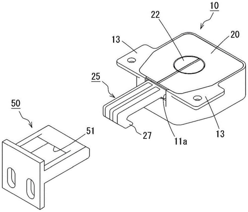
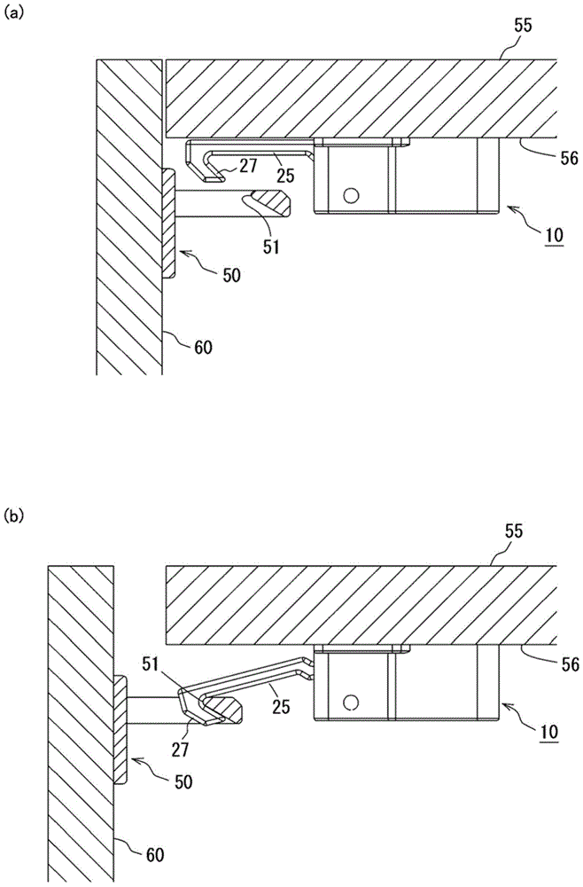
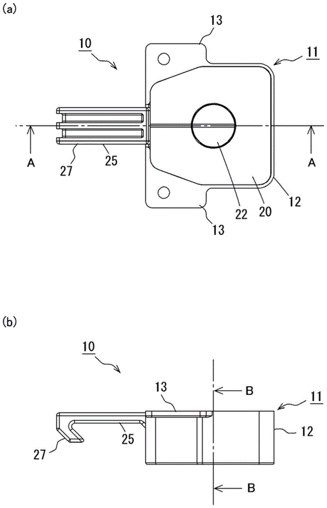
[0042] Such as figure 1 As shown, the shockproof latch mechanism 10 of this embodiment is used to engage with the receiving portion 50 to lock the door body 60 so that the door body 60 does not open. For example, if figure 2 As shown, the receiving portion 50 is fixed on the inner side of the door body 60, and the anti-shock latch mechanism 10 is fixed on the top surface of the top plate portion 56 of the frame body 55, so that the receiving portion 50 and the anti-shock latch mechanism 10 are arranged oppositely. A hook 27 protrudes from the opening 11a of the housing 11 of the shockproof latch mechanism 10, and when the hook 27 swings in the closed state of the door body 60, the hook 27 is arranged to engage with the hook engaging portion 51 of the receiving portion 50. . When vibration such as an earthquake occurs in this state, the internal mechanism of the shock-resistant ...


PUM


Abstract

An earthquake-proof latch mechanism includes a case body, a hook member which is swingably supported on the case body, and a pendulum member which is vibratably suspended and supported on the case body. The hook member includes a hook on one side of a swinging shaft and a pendulum engagement portion on the other side of the swing shaft. A through hole is formed in the pendulum engagement portion. The pendulum member is disposed to penetrate the through hole, and a peripheral surface of the pendulum member facing the through hole is formed into a tapered shape. The peripheral surface pushes up the inner periphery of the through hole to swing the hook member when the pendulum member vibrates. Thus, the earthquake-proof latch mechanism is made compact.

Description

technical field [0001] The invention relates to a shock-resistant latch mechanism that engages with a receiving portion provided on a door body when vibration occurs, and locks the door body so that the door body does not open. Background technique [0002] Conventionally, a vibration-resistant latch has been used as a mechanism for preventing doors such as sliding doors and hinged doors from accidentally opening when an earthquake occurs and contents flying out. [0003] For example, Patent Document 1 discloses a structure in which a ball is housed in a vibration region of the device body attached to the frame body side so that the ball can vibrate, and the hook is pushed up by the action of the ball to lock the door body. open (open). [0004] prior art literature [0005] patent documents [0006] Patent Document 1: Japanese Patent Laid-Open No. 2008-82167 Contents of the invention [0007] The problem to be solved by the invention [0008] However, in the structu...

Claims


Application Information

Patent Timeline
Patent Type & Authority Patents(China)
IPC IPC(8): E05C21/02
CPCE05B2063/0095E05C19/12Y10T292/0945
Inventor 青野信行
Owner MARUYOSHI INDS
Why Eureka
Try Eureka