

A small sewage sedimentation device
A sedimentation device and sewage technology, applied in the field of sedimentation, can solve the problems of difficult miniaturization and huge implementation projects, and achieve the effect of low cost and high sedimentation efficiency
- Summary
- Abstract
- Description
- Claims
- Application Information
AI Technical Summary
Problems solved by technology
Method used
Image

Examples
Embodiment 1
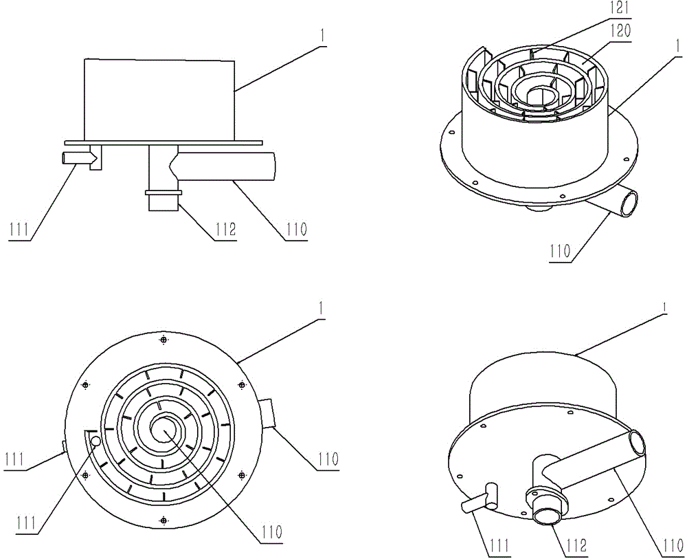
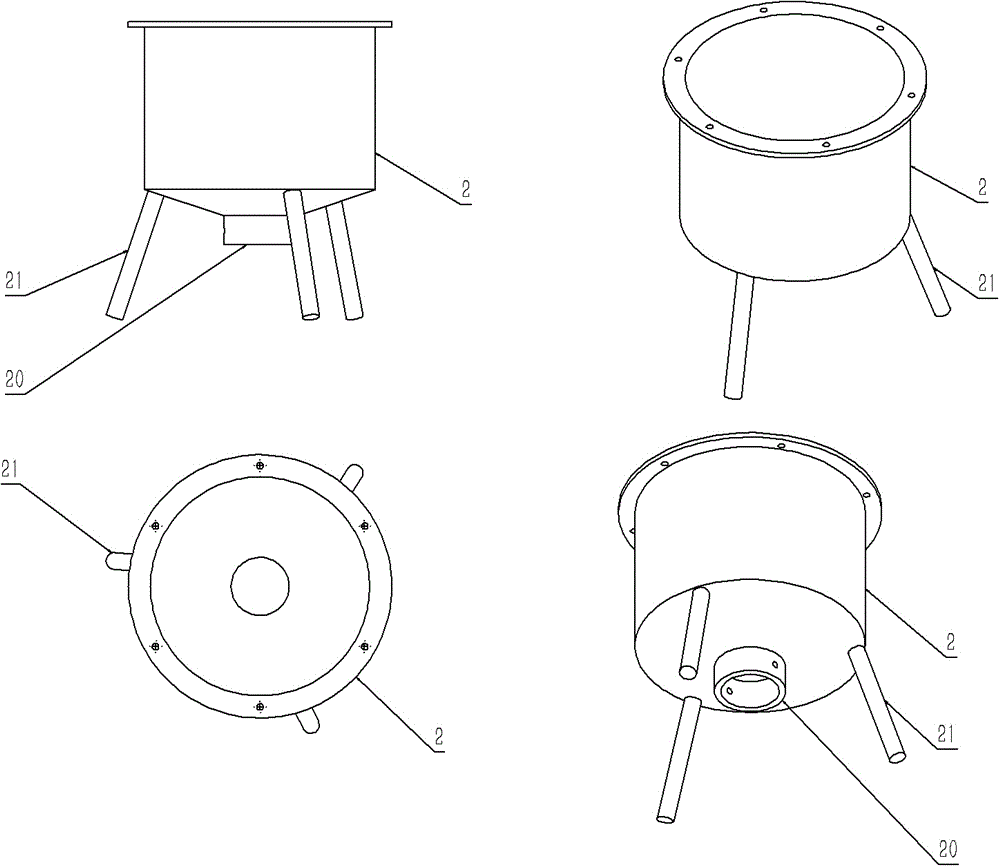
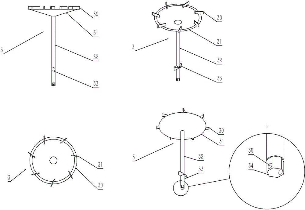
[0015] Implementation example 1, as attached Figure 1-10 As shown, this implementation example is mainly composed of a vortex waterway upper cover 1, a container 2, a vortex waterway lower cover 3, a position adjustment cylinder 5, a shaker 4, 6, and a sludge valve 7, 8; the vortex waterway upper cover 1 has Vortex water channel 120, multiple barrier plates 121, water inlet 111, water outlet 110, adjustment port 112, the diameter of water inlet 111 is smaller than water outlet 110, and the height of water inlet 111, water outlet 110 is lower than the adjustment port 112 , the barrier plates 121 are distributed on the far-center side of the vortex-shaped waterway 120, one end of all the barrier plates 121 is connected to the inner side of the far-center side of the vortex-shaped waterway 120, and the other ends of all the barrier plates 121 point to and do not touch the inner wall of the proximal side of the vortex-shaped waterway 120; The container 2 has a bottom with a sludg...
PUM
 Abstract
Description
Claims
Application Information