Die cushion force setting apparatus

一种缓冲设备、缓冲力的技术,应用在压力机、冲压机、制造工具等方向,能够解决难提供模具缓冲力精确分布等问题,达到容易输入、平稳模具缓冲力分布的效果

Active Publication Date: 2014-12-24
AIDA ENG LTD
View PDF7 Cites 3 Cited by
  • Summary
  • Abstract
  • Description
  • Claims
  • Application Information

AI Technical Summary

Problems solved by technology

In addition, there are problems because it is difficult to apply a strong die cushion force or a weak die cushion force to a specific forming area of ​​a drawn product having a complicated shape, and also because the total die cushion force is applied intermittently due to errors in human perception. In the cushion, it is therefore difficult to provide an accurate distribution of the die cushioning forces in the plane of the cushion for drawn parts with complex shapes

Method used


Image

  • Die cushion force setting apparatus
  • Die cushion force setting apparatus
  • Die cushion force setting apparatus

Examples


Embodiment Construction

[0029] Preferred embodiments of the die cushion force setting device according to the present invention will be described in detail below with reference to the accompanying drawings.

[0030] First, the die cushioning device of the press machine produced by the die cushioning force setting device according to the present invention will be described.

[0031]

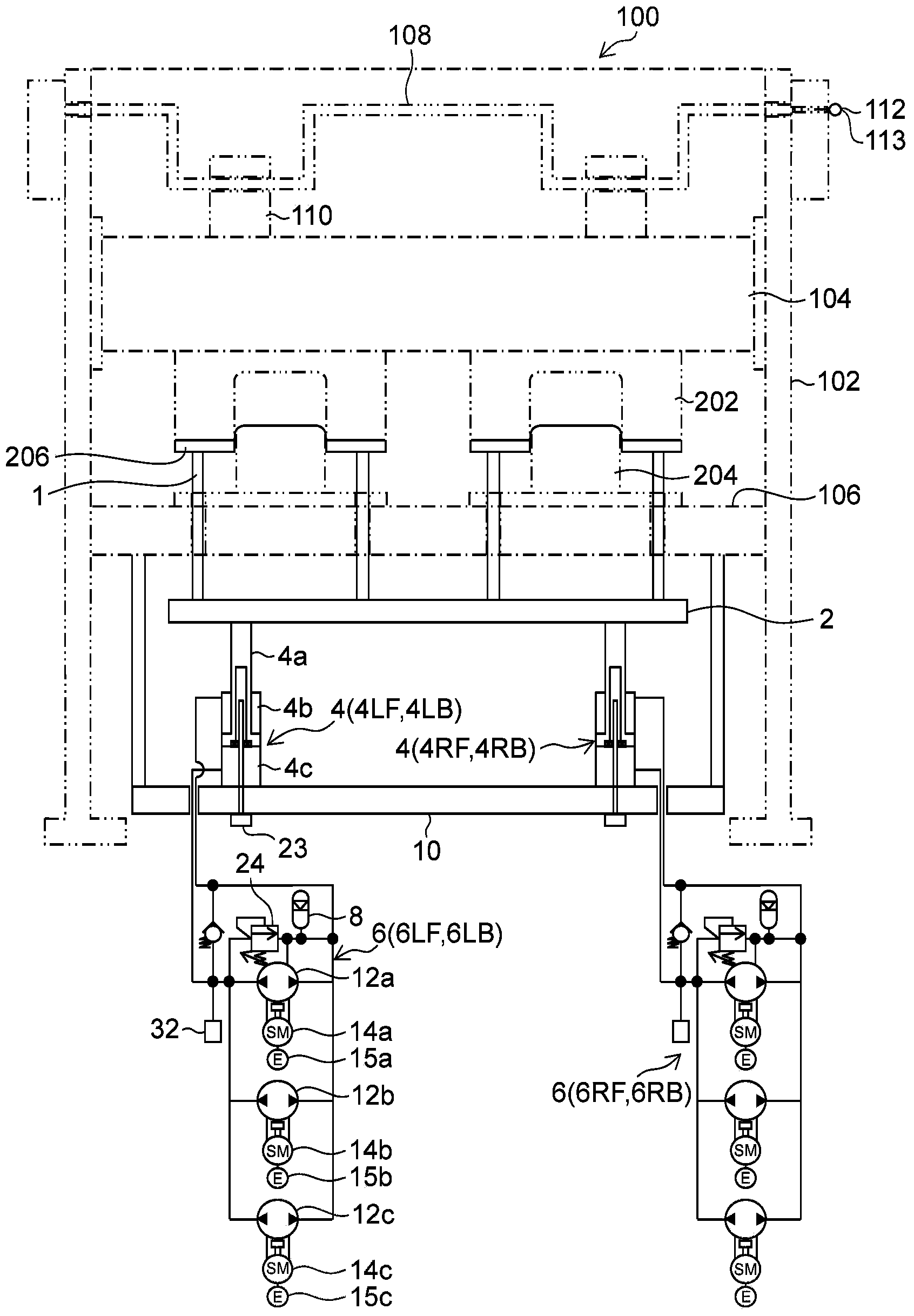
[0032] figure 1 is a block diagram showing one example of a die cushioning device of a press. The main elements of the press are indicated by dotted lines.

[0033] figure 1 The press 100 shown in includes a column (framework) 102, a slide device 104, a bed 106, a crankshaft 108, and a connecting rod 110, and the slide device 104 is movably moved in the vertical direction by a guide unit installed on the column 102. guide. Furthermore, the crankshaft 108 is connected to the sliding device 104 via a connecting rod 110 . The rotational driving force is designed to be transmitted to the crankshaft 108 by the servomot...


PUM


Abstract

The die cushion force setting apparatus according to an aspect of the present invention allows die cushion forces (component forces) acting on plural driving shafts (4a) to be set easily, makes it easy to apply strong or weak die cushion forces to a complex-shaped drawn part in a plane of a cushion pad (2), and provides a smooth die cushion force distribution. An operator manually enters (step S18A) a total die cushion force, axial component force of a left front hydraulic cylinder (4LF), and center-of-force position by operating an input device (A1). Based on the information entered via the input device (A1), the numerical computing device B1 calculates (step S18B) axial component forces of three hydraulic cylinders (4LB, 4RF, 4RB) through numerical computations. The one axial component force thus entered and three axial component forces thus computed numerically are set (step S18C) as the axial component forces of four hydraulic cylinders (4LF, 4LB, 4RF, 4RB).

Description

technical field [0001] The present invention relates to a mold cushioning force setting device, and more particularly to a mold cushioning force setting device suitable for separately setting a mold cushioning force (component force), wherein the mold cushioning force acts on a supporting mold cushioning device Cushion pads for multiple drive shafts. Background technique [0002] Conventionally, a die cushion pin pressure control device has been proposed for a die cushion device that supports a cushion using a plurality of hydraulic cylinders in which the hydraulic cylinders are divided into a plurality of groups, and a hydraulic supply line is installed for each group to transfer the hydraulic pressure Force is supplied to the group from a hydraulic pressure supply device, a hydraulic pressure adjustment mechanism (pressure control valve) is provided in each hydraulic supply line, and the mold cushion pressure is independently controlled for each hydraulic cylinder (Japanes...

Claims


Application Information

Patent Timeline
Patent Type & Authority Applications(China)
IPC IPC(8): B21D24/02
CPCB21D24/10B30B1/26B30B15/061B30B15/14B21D24/02G05B19/46
Inventor 河野泰幸土田师文真壁纯司
Owner AIDA ENG LTD
Why Eureka
Try Eureka