Control device

Active Publication Date: 2013-11-21
AISIN AW CO LTD
View PDF2 Cites 31 Cited by
  • Summary
  • Abstract
  • Description
  • Claims
  • Application Information

AI Technical Summary

Benefits of technology

[0023]With this configuration, it is possible to identify the inputs to the current feedback control system as a sinusoidal wave or cosinusoid

Problems solved by technology

However, the control device for the rotating electrical machine uses a proportional-plus-integral (PI) controller such that DC current commands are tracked, so there occur a delay in response to the fluctuating commands.
Therefore, in JP 2006-033969 A, an actual output torque and actual currents respectively track the fluctuating torque command and the fluctuating current commands with a

Method used


Image

  • Control device
  • Control device
  • Control device

Examples


first embodiment

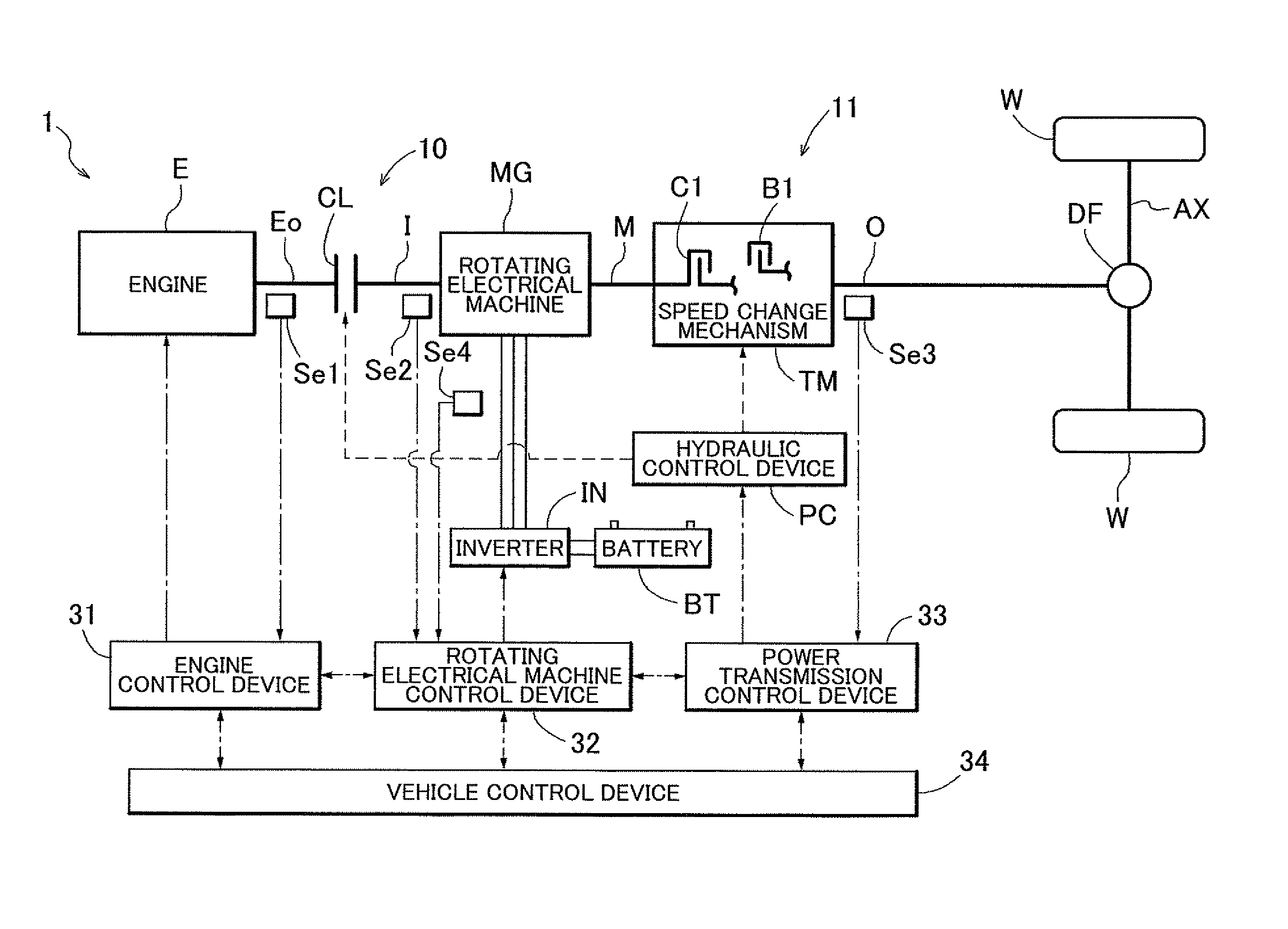
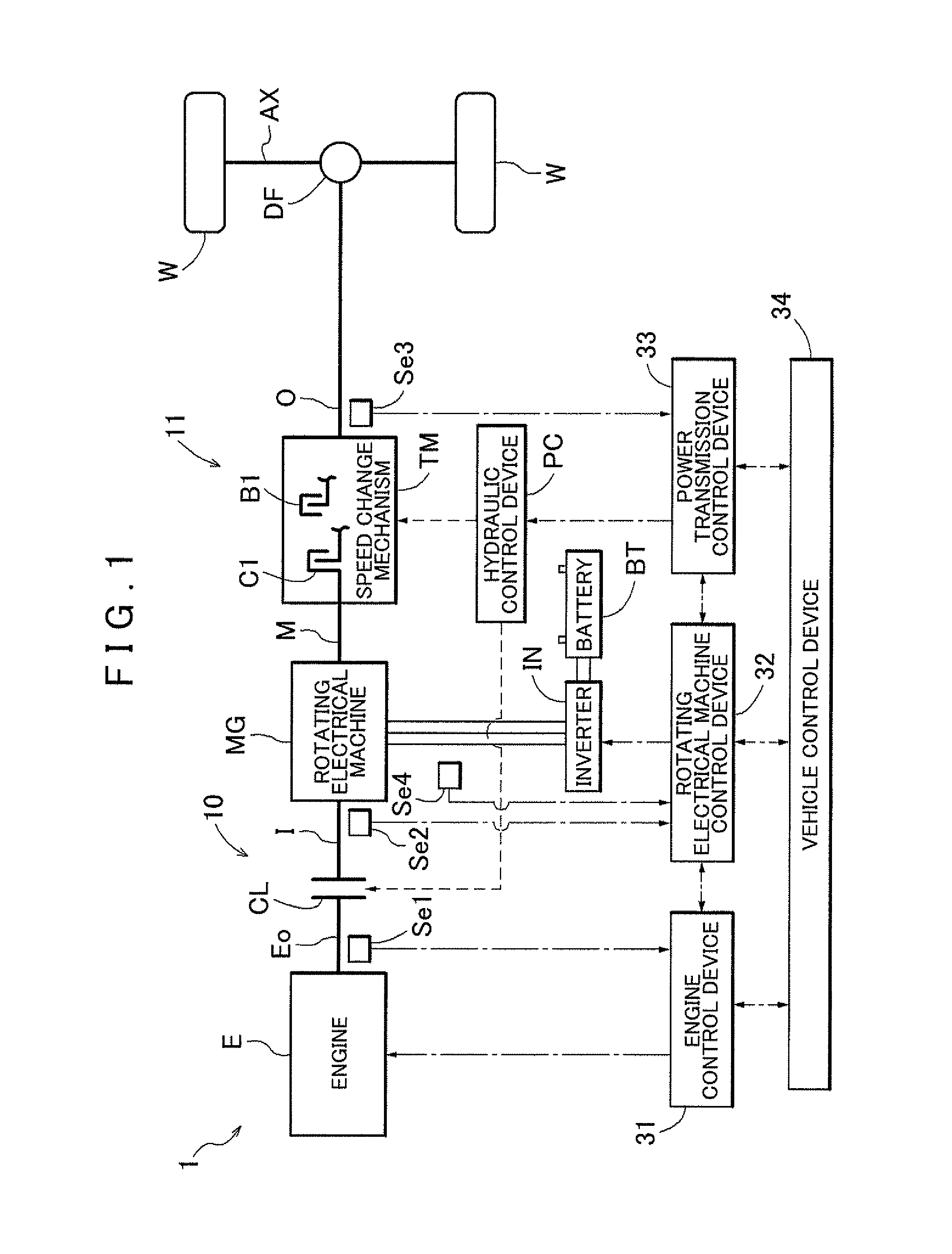
[0042]An embodiment of a rotating electrical machine control device 32 according to the present invention will be described with reference to the accompanying drawings. FIG. 1 is a schematic view that shows the schematic configuration of a vehicle driving system 1 according to the present embodiment. As shown in the drawing, a vehicle on which the vehicle driving system 1 is mounted is a hybrid vehicle that includes an engine E, which is an internal combustion engine, and a rotating electrical machine MG as driving force sources of the vehicle. In the drawing, the wide solid lines indicate transmission paths of driving force, the dashed lines indicate supply paths of hydraulic fluid, the alternate long and short dashed lines indicate transmission paths of signals, and the narrow solid lines indicate transmission paths of electric power. The rotating electrical machine MG is drivably coupled to the engine E, and is drivably coupled to wheels W. In the present embodiment, the rotating...


PUM


Abstract

A control device for a rotating electrical machine, which is able to reduce a tracking delay of an actual output torque and actual currents with respect to a fluctuating torque command and fluctuating current commands and to reduce steady state deviations, is obtained. The control device includes a torque current computing unit; an actual current computing unit; a current feedback control unit; and a voltage control unit that controls voltages on the basis of the two-phase voltage commands. The torque command includes a fluctuation cancellation torque command for cancelling transmission torque fluctuations transmitted from the internal combustion engine, and the current feedback control unit includes a harmonic controller that calculates the two-phase voltage commands by using a characteristic of a transfer function corresponding to a periodic function of a frequency of the transmission torque fluctuations.

Description

INCORPORATION BY REFERENCE[0001]The disclosure of Japanese Patent Application No. 2011-068144 filed on Mar. 25, 2011 including the specification, drawings and abstract is incorporated herein by reference in its entirety.BACKGROUND OF THE INVENTION[0002]The present invention relates to a control device used to control a rotating electrical machine that is drivably coupled to an internal combustion engine and that is drivably coupled to a wheel.DESCRIPTION OF THE RELATED ART[0003]For the above-described control device, for example, Japanese Patent Application Publication No. 2006-33969 (JP 2006-033969 A) describes a technique for causing a rotating electrical machine to output a torque for damping torque fluctuations that are transmitted from an internal combustion engine. At this time, a torque command intended for the rotating electrical machine is a torque command that is opposite in phase to the transmission torque fluctuations.[0004]In addition, in order to reduce a torque ripple...

Claims


Application Information

Patent Timeline
IPC IPC(8): H02P21/05B60L50/16
CPCH02P21/05B60K6/48B60W10/08B60W20/00B60W2050/0008B60W2050/0041B60W2510/083B60W2710/08B60W2710/083H02P21/06B60L15/025B60L2240/421B60L2240/423B60L2240/427B60L2240/429B60L2240/443B60L2240/461B60L2240/529B60L2240/527B60W30/20B60W2030/206Y02T10/40Y02T10/62Y02T10/64Y02T10/72
Inventor KOBAYASHI, HIROKAZUSHIMADA, ARINORIAOKI, TAKESHISAHA, SUBRATAIWATSUKI, KEN
Owner AISIN AW CO LTD
Why Eureka
Try Eureka