
Embroidery machine

An embroidery machine and embroidery technology, applied in embroidery machines, embroidery machine mechanisms, textiles and papermaking, etc., can solve problems such as the complexity of the drive source structure, and achieve the effect of a simple structure

Inactive Publication Date: 2014-12-24
CANDART
View PDF9 Cites 0 Cited by
  • Summary
  • Abstract
  • Description
  • Claims
  • Application Information

AI Technical Summary

Problems solved by technology

[0010] However, each embroidery head of the embroidery machine has a plurality of embroidery needles and complicated mechanisms such as a needle bar driving part, a balance, and a tensioning part respectively arranged correspondingly to them.
Therefore, when adjusting the tension of the upper thread as described in the above-mentioned Patent Documents 1 to 3, the structure of the driving source for tension adjustment becomes more complicated.

Method used


Image

  • Embroidery machine
  • Embroidery machine
  • Embroidery machine

Examples


Embodiment Construction

[0078] Hereinafter, an embroidery machine according to an embodiment of the present invention will be described in detail with reference to the drawings.

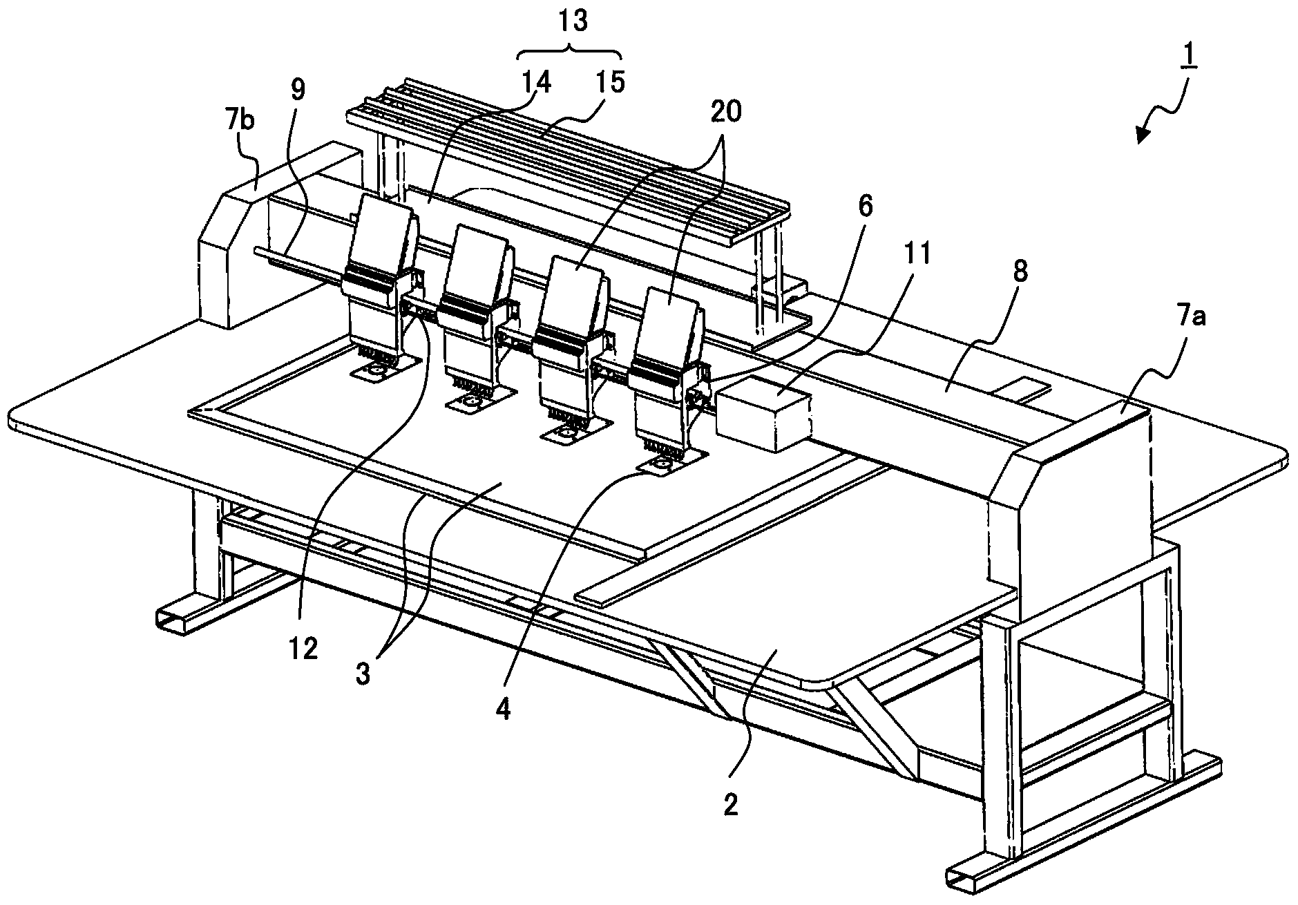
[0079] figure 1 It is a perspective view showing the embroidery machine 1 according to one embodiment of the present invention.

[0080] figure 1 The illustrated embroidery machine 1 is provided with an embroidery machine table 2 and an embroidery frame 3 extending widely at the center of the embroidery machine table 2 .

[0081] On the lower side of the embroidery frame 3, there are multiple figure 1 In the example is 4) lower shuttle part 4. After the embroidery medium is tensioned and set, the embroidery frame 3 can freely move forward, backward, left, and right according to the procedure in the embroidery instruction book.

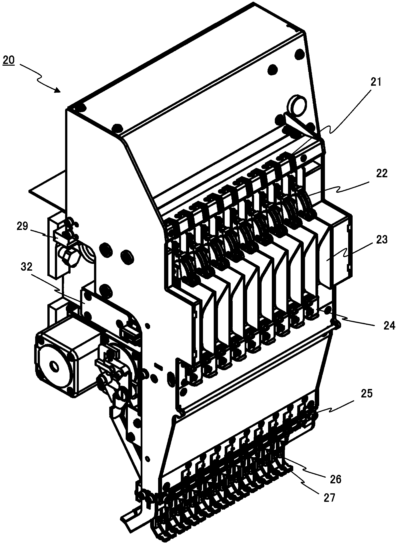
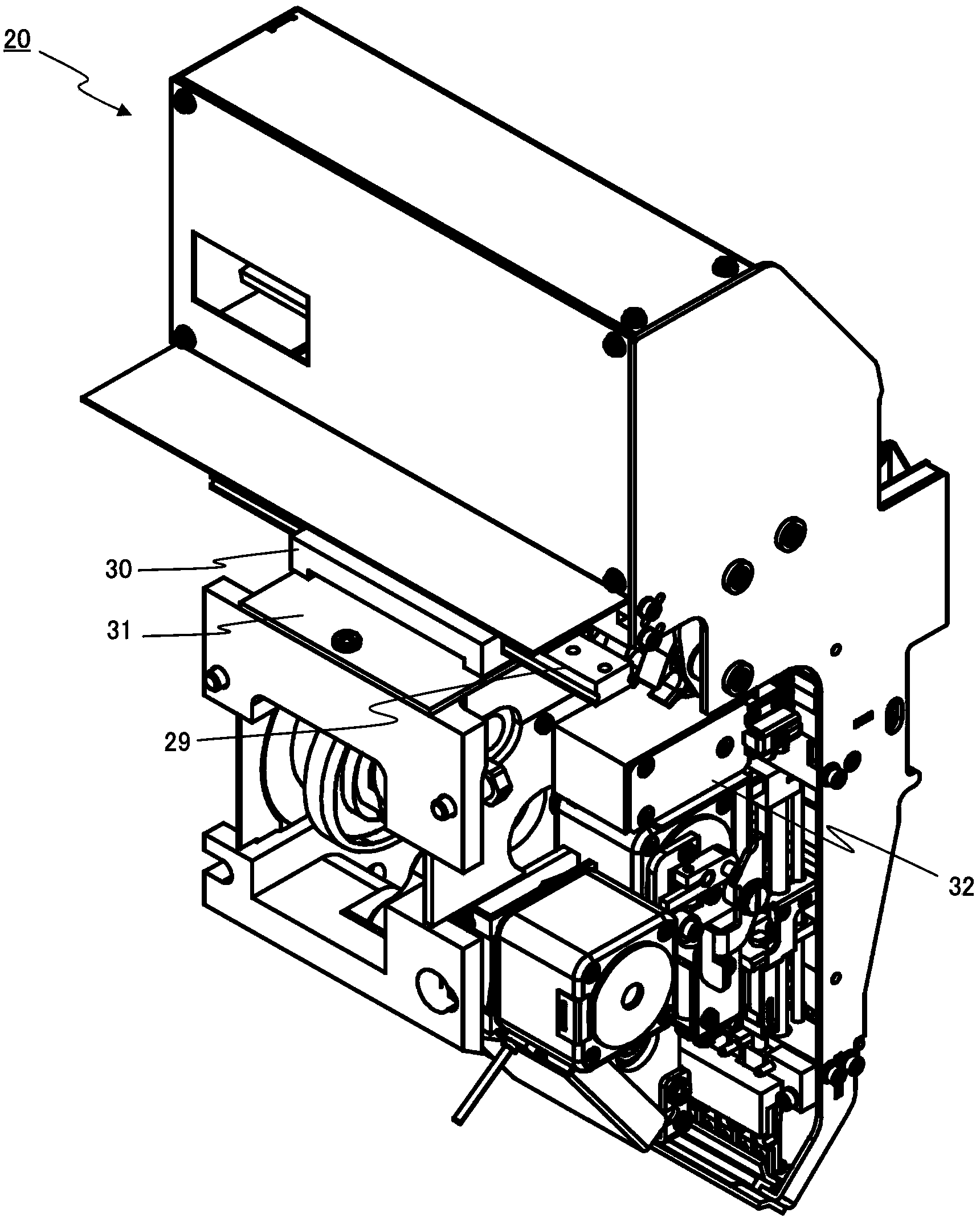
[0082] In the upper position corresponding to the lower shuttle part 4, there are multiple figure 1 In the example, there are four) the embroidery head 20 described later, the head rail of the ...


PUM


Abstract

The invention provides an embroidery machine. A tension of a surface wire is adjusted by utilization of a simple structure in the embroidery machine. The embroidery machine comprises a plurality of embroidery needles, a plurality of tension sections (digital variable tension sections (24)) and a driving section (an electromagnetic solenoid (32), a driving arm (33) and an action shaft (35)). Surface wires are inserted into the plurality of embroidery needles. The tension sections applies a tension to the surface wires inserted into the plurality of embroidery needles. The plurality of embroidery needles move transversely during selection and buckle with the plurality of tension sections (digital variable tension sections (24)) alternatively. The driving section provides power to the buckled tension sections (digital variable tension sections (24)).

Description

technical field [0001] The present invention relates to an embroidery machine having a tensioning part that applies tension to an upper thread. Background technique [0002] Conventionally, with regard to embroidery machines, the thickness, material, and color of threads used are different, and the thickness and material of embroidery objects such as cloth are also different. Therefore, a method has been proposed in which a tension of the upper thread is applied to the thread path of each embroidery needle on an embroidery head in which a plurality of embroidery needles are arranged (for example, refer to Patent Documents 1 to 3). [0003] Patent Document 1 describes a method of switching the tension of the upper thread between two modes, a strong mode and a weak mode, using a pulse motor. [0004] Patent Document 2 describes a method of turning on / off the tension of the noodle thread using an electronic solenoid. [0005] Patent Document 3 describes a method of controllin...

Claims


Application Information

Patent Timeline
Patent Type & Authority Applications(China)
IPC IPC(8): D05C11/10
CPCD05C11/10
Inventor 日下部健次
Owner CANDART
Features
  • Generate Ideas
  • Intellectual Property
  • Life Sciences
  • Materials
  • Tech Scout
  • Unparalleled Data Quality
  • Higher Quality Content
  • 60% Fewer Hallucinations
Learn More