Conveying device for material carrying

A technology for conveying devices and materials, applied in the field of transportation, can solve problems such as poor applicability, inability to meet production needs, waste of resources, etc., and achieve the effects of convenient operation, multi-layer utilization, and improved applicability

Active Publication Date: 2020-03-27
南京奇云智能科技有限公司
View PDF9 Cites 3 Cited by
  • Summary
  • Abstract
  • Description
  • Claims
  • Application Information

AI Technical Summary

Problems solved by technology

[0003] At present, most of the existing material conveying devices use fixed conveyor belts. Since the factory often plans and changes the production line, because the length of the specific conveyor belt is fixed, the applicability is poor, and it cannot be more practical. The length of the demand is adjusted, which in turn causes a waste of resources; it cannot meet the actual production demand

Method used


Image

  • Conveying device for material carrying
  • Conveying device for material carrying

Examples


Embodiment 1

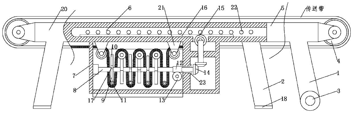
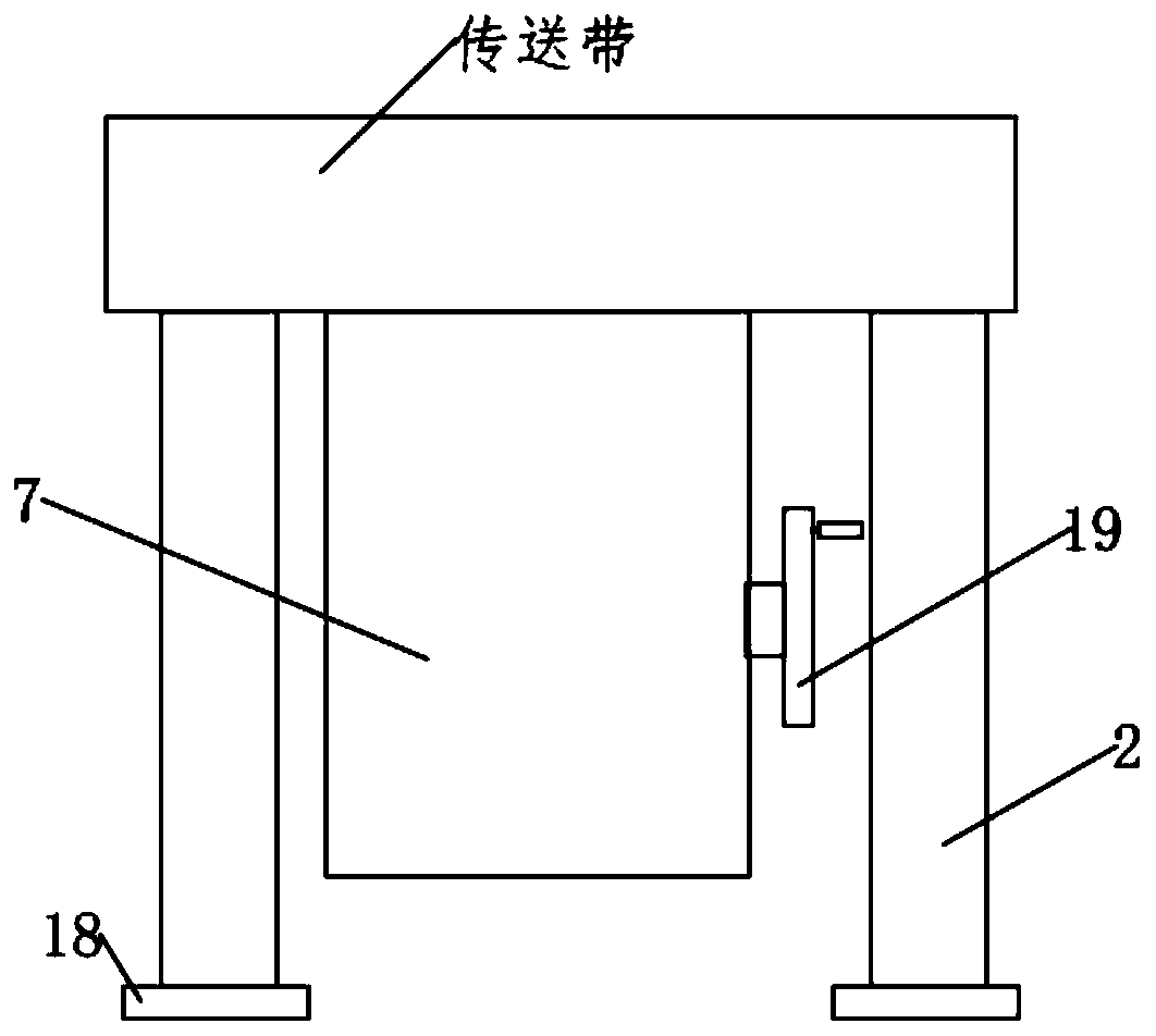
[0019] see Figure 1-2 , a conveying device for material handling, comprising a fixed bracket 20 and a fixed foot support 2, a mobile bracket 5 is slidably installed on the fixed bracket 20 through a sliding rod 6, and a rotating bracket 5 is installed on one end of the fixed bracket 20 and the mobile bracket 5 to rotate Wheel 4, and then the conveyor belt expansion account is installed on the rotating wheel 4, the bottom of the fixed bracket 2 is equipped with an adjustment box 7, and the conveyor belt passes through the adjustment box 7; the fixed foot support 2 Fixedly installed on the fixed bracket 20; the mobile bracket 5 is fixedly installed with a mobile foot support 1, and the mobile foot support 1 is rotatably equipped with a roller 3, and then the device pulls the mobile during actual use. The bracket 5 makes the sliding rod 6 slide along the fixed bracket 20, thereby adjusting the length of the conveyor belt; the adjustment box 7 is used to adjust the length and the...

Embodiment 2

[0027] In order to further improve the rotation effect of the rotating shaft 8 of the device, this embodiment makes the following improvements on the basis of the first embodiment. The improvement is that a bushing 23 is installed on the inner wall of the rotating shaft 8 and the adjustment box 7 for rotation. , the friction force between the rotating shaft 8 and the adjustment box 7 is further reduced by the bushing 23; and the rotation effect of the rotating shaft 8 is further improved.

[0028] The working principle of this embodiment: a bushing 23 is arranged between the rotating shaft 8 and the adjusting box 7, and the rotating effect of the rotating shaft 8 is improved through the reduced frictional force.


PUM


Abstract

The invention discloses a conveying device for material carrying. The conveying device comprises a fixed support and fixed kickstands; a moving support is glidingly mounted on the fixed support through a sliding rod; rotating wheels are rotationally mounted at one end of the fixed support and one end of the moving support; a conveying belt is mounted on the rotating wheels in an expanding manner;an adjusting box is laid and mounted at the bottom of the fixed support; the conveying belt penetrates through the adjusting box; the fixed kickstands are fixedly mounted on the fixed support; movingkickstands are fixedly mounted on the moving support; and rolling wheels are rotationally mounted on the moving kickstands. The conveying device is simple in structure and convenient to operate; the length of the conveying device can be adjusted effectively, so that the applicability of the conveying device is improved, and then multi-layer utilization of resources is realized; during use of the device, the length and the tension of the conveying belt are adjusted effectively, and the lengthening action of the device is not affected by the conveying belt.

Description

technical field [0001] The invention relates to the field of transportation, in particular to a conveying device for material handling. Background technique [0002] Material transportation refers to the activities carried out within the scope of the same place, with the main goal of changing the storage state and spatial location of materials. Material transportation is very important to improve the efficiency of warehouse operations, and material transportation also directly affects production efficiency. With the expansion of production scale and the improvement of automation, the material conveying equipment manufacturing industry is more and more widely used in the modern production process, and its role is becoming more and more important. [0003] At present, most of the existing material conveying devices use fixed conveyor belts. Since the factory often plans and changes the production line, because the length of the specific conveyor belt is fixed, the applicabili...

Claims


Application Information

Patent Timeline
Patent Type & Authority Applications(China)
IPC IPC(8): B65G21/14B65G23/44B65G21/00
CPCB65G21/14B65G23/44B65G21/00B65G2812/02217
Inventor 刘绍亚吴继春王红辉熊任上王晟垚
Owner 南京奇云智能科技有限公司
Why Eureka
Try Eureka