
Method for increasing condensate oil recovery ratios of condensate gas reservoirs by means of gas injection vertical displacement

A technology of condensate gas reservoir and recovery factor, which is applied in the direction of production fluid, earthwork drilling and production, wellbore/well components, etc. It can solve the problems of increasing the swept volume of gas injection, not considering the difference of fluid physical properties, and high gas-oil ratio , to achieve the effect of improving the utilization rate

Active Publication Date: 2014-12-24
PETROCHINA CO LTD
View PDF3 Cites 19 Cited by
  • Summary
  • Abstract
  • Description
  • Claims
  • Application Information

AI Technical Summary

Problems solved by technology

[0005] 1. In the current condensate gas reservoirs exploited by gas injection, the sweep coefficient of the injected gas in the formation is not high, and a large amount of injected gas reaches the bottom of the production well prematurely, resulting in an excessively high gas-oil ratio, which affects the utilization rate of the injected gas;
[0006] 2. There is a large difference in physical properties between injected gas and formation condensate gas. The current gas injection production method does not consider the difference in fluid physical properties, let alone use this difference to increase the swept volume of gas injection and make the injected gas play its role. greater effect;

Method used


Image

  • Method for increasing condensate oil recovery ratios of condensate gas reservoirs by means of gas injection vertical displacement
  • Method for increasing condensate oil recovery ratios of condensate gas reservoirs by means of gas injection vertical displacement
  • Method for increasing condensate oil recovery ratios of condensate gas reservoirs by means of gas injection vertical displacement

Examples


Embodiment 1

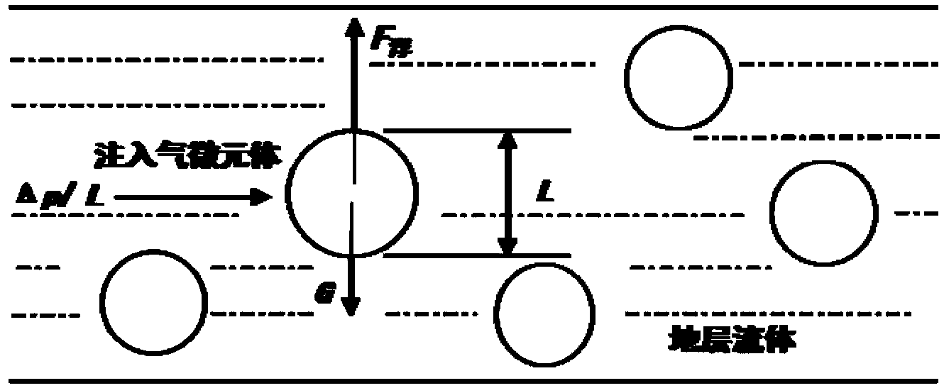
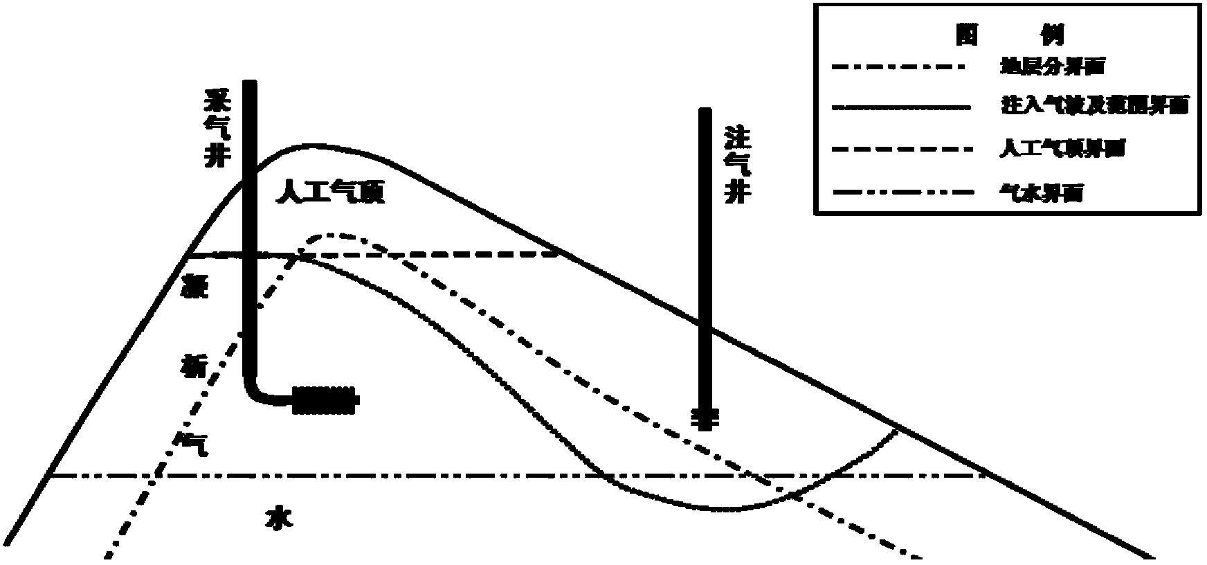
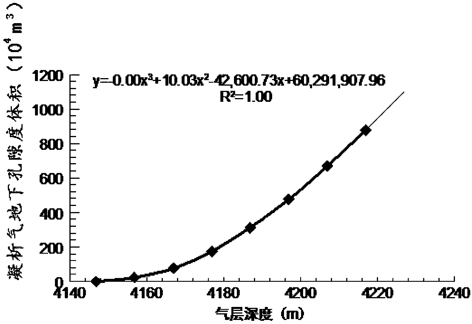
[0042] Embodiment 1: as figure 1 , figure 2 , image 3 , Figure 4 and Figure 5 As shown in Fig. 1, a method for enhancing condensate oil recovery in condensate gas reservoirs by vertical displacement of gas injection,

[0043] Aiming at the above three major problems in the exploitation of condensate gas reservoirs by gas injection, a method for improving condensate oil recovery in condensate gas reservoirs by vertical displacement of gas injection is provided; The difference in fluid physical properties can improve the sweep coefficient of injected gas in the formation and can effectively reduce the occurrence of gas channeling, and ultimately can significantly improve the utilization rate of injected gas and the ultimate recovery of condensate oil.

[0044] Taking the injection-production well group Y of a certain gas reservoir as an example, there is currently an injection well A in the injection-production well group, and two production wells are located at the east...


PUM


Abstract

The invention discloses a method for increasing condensate oil recovery ratios of condensate gas reservoirs by means of gas injection vertical displacement, and belongs to the technical field of condensate gas field development. The method includes selecting proper injected gas according to a principle that a gravitational differentiation phenomenon is obvious when a density ratio of the preferable injected gas to fluid of the gas reservoirs is lower than 0.75 under a formation condition in gas injection physical model experiments and actual production; determining injection and production well locations, perforation intervals, well patterns and well spacing by the aid of a kinetic mechanical analysis process for micro-elements of the injected gas so as to effectively form artificial gas caps in gas injection procedures; determining critical gas production rates according to a critical production rate correction formula. The critical gas production rates are used for preventing increase of gas-oil ratios due to coning of the injected gas. The method has the advantages that the artificial gas caps can be formed at high structural positions by the injected gas, condensate gas can be subjected to vertical downward displacement by the aid of the injected gas, accordingly, the sweep efficiency of the injected gas is close to 100%, and the injected gas utilization rate and the final condensate oil recovery ratios can be obviously increased.

Description

technical field [0001] The invention relates to a method for increasing the recovery rate of condensate oil in condensate gas reservoirs by gas injection vertical displacement, and belongs to the technical field of condensate gas field development. Background technique [0002] In the 1930s, the United States was the first to develop condensate gas reservoirs, initially using depletion mining, and gradually explored and implemented gas injection mining in the 1940s; the exploitation of condensate gas reservoirs in my country was more than 40 years later than that in the United States. At the beginning of the 1990s, condensate gas reservoirs such as Bajiaochang in Sichuan, Banqiao in Dagang, Panjin in Liaoning, Kekeya in Xinjiang, and Yaha began to be discovered successively; the initial condensate gas fields basically adopted depletion mining; In the process of conventional mining, the formation pressure gradually decreases. When the formation pressure drops below the dew poin...

Claims


Application Information

Patent Timeline
IPC IPC(8): E21B43/24
Inventor 江同文朱忠谦阳建平谢伟徐文圣王勇
Owner PETROCHINA CO LTD
Learn More