Speed reducer thrust bearing structure
A thrust bearing and reducer technology, applied in transmission parts, belts/chains/gears, mechanical equipment, etc., can solve problems such as thrust bearing damage, and achieve the effects of high degree of automation, good general performance and wide application range.
Inactive Publication Date: 2014-12-24
尹克华
View PDF0 Cites 1 Cited by
- Summary
- Abstract
- Description
- Claims
- Application Information
AI Technical Summary
Problems solved by technology
[0002] The thrust bearing structure of the reducer is an important part in mechanical transmission. The thrust bearing of the reducer plays the role of matching the speed and transmitting torque between the prime mover and the working machine or the actuator. It is widely used in modern machinery. However, at present The thrust bearing does not have a torque limiting function, so it is prone to overload and damage to the thrust bearing
Method used
View moreImage
Smart ImageViewing Examples

Examples
Embodiment Construction
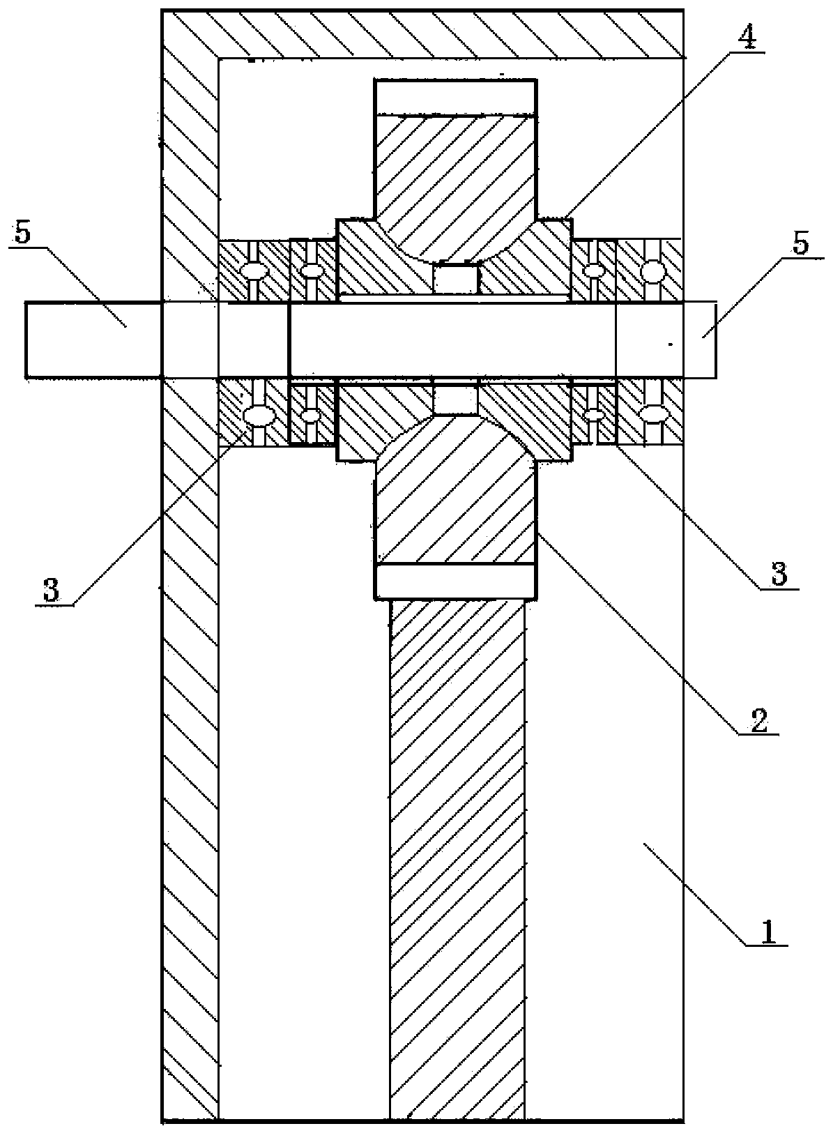
[0009] The thrust bearing structure of the reducer has a gear box (1), an unstaged gear (2) is installed in the inner cavity of the gear box (1), a disc spring (4) is installed on the unstaged gear (2), and a disc spring (4) is installed on the unstaged gear (2). Two pairs of thrust bearings (3) are installed symmetrically on both sides of the shape spring (4), and an output shaft (5) is installed in the inner holes of the thrust bearing (3) and the disk spring (4).
Login to View More PUM
 Abstract
The invention discloses a speed reducer thrust bearing structure. A last-stage gear is mounted in an inner cavity of a gear box, a dish-shaped spring is mounted on the last-stage gear, two pairs of thrust bearings are symmetrically mounted on two sides of the dish-shaped spring, and an output shaft is mounted in inner holes of the thrust bearings and the dish-shaped spring. The speed reducer thrust bearing structure has the advantages of compact structure, high automation level, good universality and wide using range, and the defect that thrust bearings are prone to being damaged caused by overload due to the fact that existing speed reducer thrust bearing structures do not have torque limiting functions is overcome effectively.
Description
technical field [0001] The invention relates to a thrust bearing structure, in particular to a thrust bearing structure of a reducer, and belongs to the technical field of mechanical transmission. Background technique [0002] The reducer thrust bearing structure is an important component in mechanical transmission. The reducer thrust bearing plays the role of matching the rotational speed and transmitting torque between the prime mover and the working machine or the actuator, and is widely used in modern machinery. However, at present, The thrust bearing does not have a torque limiting function, so it is prone to overload and damage to the thrust bearing. SUMMARY OF THE INVENTION [0003] The purpose of the present invention is to provide a reducer thrust bearing structure with compact structure, high degree of automation, good general performance and wide application range, so as to overcome the above-mentioned defects of the existing reducer thrust bearing. [0004] Th...
Claims
Login to View More Application Information
Patent Timeline
 Patent Type & Authority Applications(China)
IPC IPC(8): F16H57/021F16H57/023
CPCF16H57/021F16H57/023
Inventor 尹克华
Owner 尹克华

PatSnap Eureka turns technology decisions into work you can execute. Powered by our Innovation Knowledge Graph, it runs expert workflows across engineering, life sciences, materials and intellectual property. Get your review-ready output in minutes.


