Photographic equipment, photographic equipment control method, photographic equipment system
A photographic equipment and photographic parameter technology, applied to parts of TV systems, parts of color TVs, instruments, etc., can solve problems such as simplification of operation, convenience of intuitive operation and fine-tuning, configuration of multiple operating parts, etc. , to achieve the effect of preventing misoperation
- Summary
- Abstract
- Description
- Claims
- Application Information
AI Technical Summary
Problems solved by technology
Method used
Image
Examples
no. 1 Embodiment approach
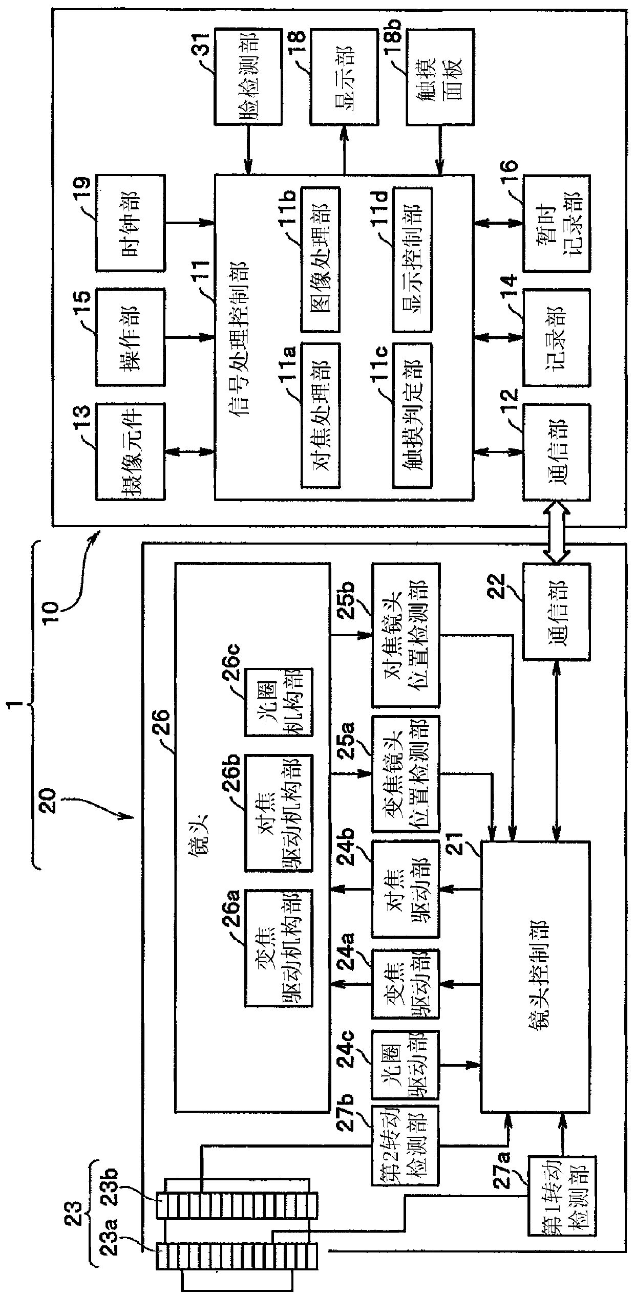
[0053] First, a schematic configuration of an imaging device (hereinafter simply referred to as a camera) according to a first embodiment of the present invention will be described below. figure 1 It is a block configuration diagram showing a schematic of an internal main configuration of an imaging device (camera) according to the first embodiment of the present invention.
[0054] Such as figure 1 As shown, the camera 1 of this embodiment is composed of a camera body 10 and a lens barrel 20 . The camera 1 is a so-called interchangeable lens camera in which a lens barrel 20 is detachably attached to a camera body 10 . In this embodiment, an interchangeable-lens camera is used as an example of the imaging device for description. However, the camera of the imaging device to which the present invention can be applied is not limited to this type. For example, the camera body 10 and the lens barrel 20 are integrally formed. Fixed-lens cameras can also be used in exactly the same...
no. 2 Embodiment approach
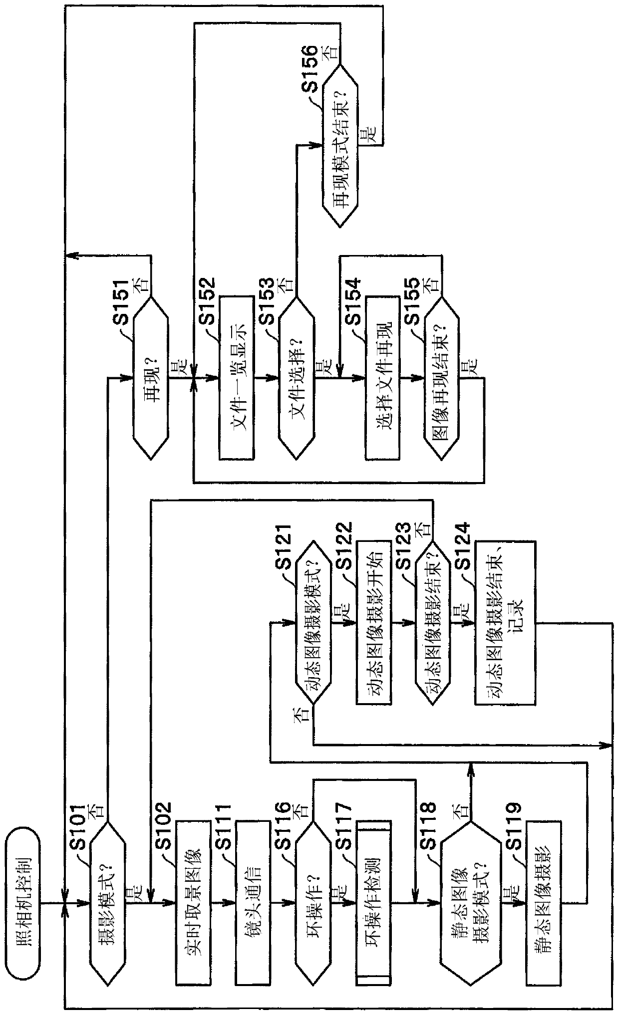
[0156] In the second embodiment of the present invention described below, an example in which the display method in the zoom fine adjustment mode is different from that of the first embodiment described above is shown. The basic configuration of the imaging device (camera) itself of this embodiment is substantially the same as that of the above-mentioned first embodiment, and only the camera control sequence is slightly different. Therefore, the same configuration as that of the above-mentioned first embodiment will be omitted from illustration, and will be described using the same reference numerals. Also, illustration and description of the same processing sequence will be omitted, and only the different parts will be described below.
[0157] Figure 8 It is a flowchart showing the camera control processing sequence in the imaging device (camera) according to the second embodiment of the present invention. and, Figure 9 ~ Figure 14 This is an example of display on the d...
no. 3 Embodiment approach
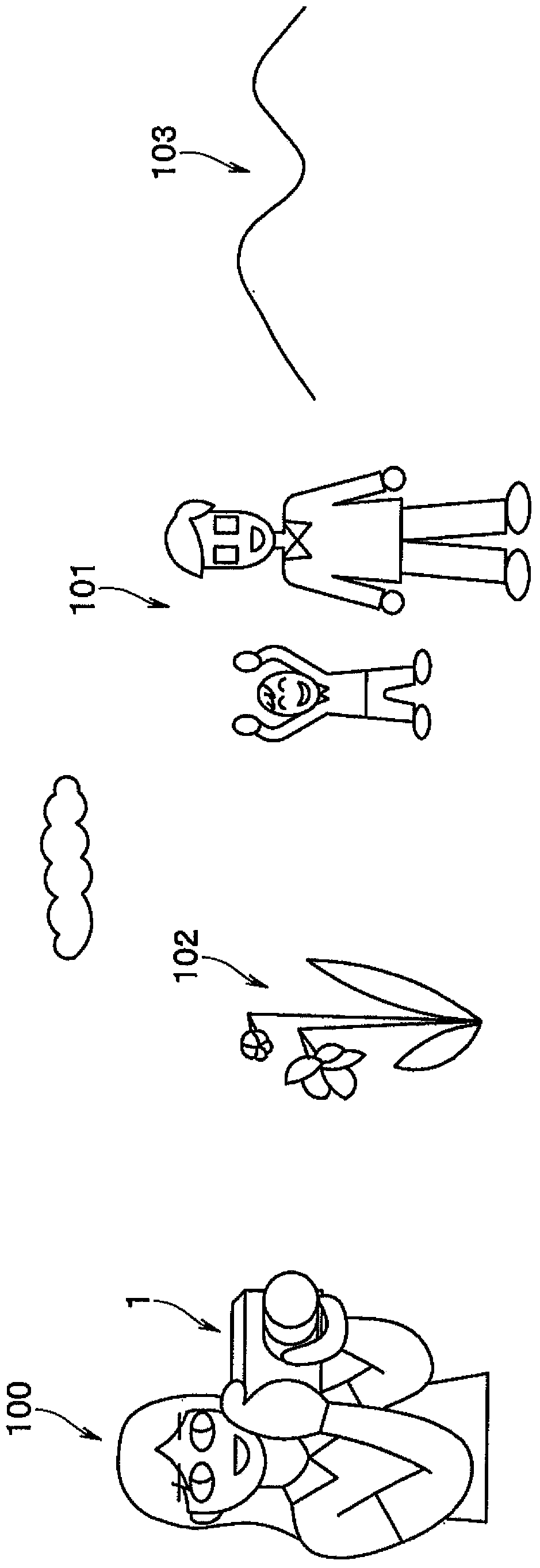
[0206] Next, a third embodiment of the present invention will be described below. This embodiment shows an example of one form of focus control applied to an imaging device (camera) having substantially the same configuration as the above-described embodiments. Therefore, the basic configuration of the imaging device (camera) itself of this embodiment is the same as that of the above-mentioned first embodiment, and only the camera control sequence is slightly different. Therefore, for the same configuration as that of the above-mentioned first embodiment, illustration is omitted, and reference is made to figure 1 , figure 2 Descriptions are made using the same reference numerals. Also, regarding the same processing sequence (refer to image 3 ), the diagrams and descriptions are also omitted, and only the different parts are described below.
[0207]Focus control (focus alignment, focus control, and focus adjustment) in the camera 1 , which is the imaging device of the pr...
PUM
 Abstract
Description
Claims
Application Information
 - R&D
- Intellectual Property
- Life Sciences
- Materials
- Tech Scout
- Unparalleled Data Quality
- Higher Quality Content
- 60% Fewer Hallucinations
Browse by: Latest US Patents, China's latest patents, Technical Efficacy Thesaurus, Application Domain, Technology Topic, Popular Technical Reports.
© 2025 PatSnap. All rights reserved.Legal|Privacy policy|Modern Slavery Act Transparency Statement|Sitemap|About US| Contact US: help@patsnap.com


