Application method of mixed permanent magnets in flux-switching permanent magnet motor

A permanent magnet motor and magnetic flux switching technology, which is applied to the magnetic circuit characterized by magnetic materials, the static parts of the magnetic circuit, and the shape/style/structure of the magnetic circuit, which can solve the high manufacturing cost of the magnetic flux switching permanent magnet motor. , The motor torque density is reduced, the cogging torque and the magnetic flux density are high, so as to reduce the risk of irreversible demagnetization, reduce the manufacturing cost, and alleviate the degree of magnetic saturation.

Inactive Publication Date: 2014-12-24
HEBEI UNIV OF TECH
View PDF6 Cites 36 Cited by
  • Summary
  • Abstract
  • Description
  • Claims
  • Application Information

AI Technical Summary

Problems solved by technology

[0004] The technical problem to be solved by the present invention is to provide the application method of the hybrid permanent magnet in the flux switching permanent magnet motor, and use the hybrid permanent magnet connected by two kinds of permanent magnets with different magnetic properties in the stator of the flux switching permanent magnet motor. Magnet, that is, a rare earth permanent magnet with high energy product is installed near the stator yoke of the motor, and a ferrite permanent magnet with low energy product and low price is installed near the teeth of the motor stator, which overcomes the magnetic flux switching of the prior art The manufacturing cost of permanent magnet motors is too high, and the use of permanent magnets with high magnetic energy product makes the magnetic flux density generated by the teeth of the motor stator too high, which leads to serious magnetic saturation of the teeth, resulting in a decrease in the torque density of the motor and a very large cogging torque.

Method used


Image

  • Application method of mixed permanent magnets in flux-switching permanent magnet motor
  • Application method of mixed permanent magnets in flux-switching permanent magnet motor
  • Application method of mixed permanent magnets in flux-switching permanent magnet motor

Examples


Embodiment 1

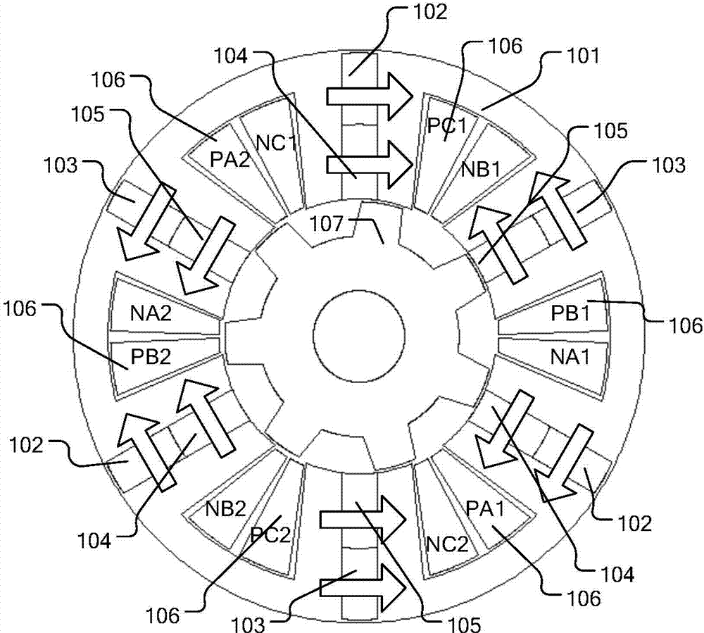
[0041]Install N35 NdFeB permanent magnets with high magnetic energy product at the position close to the yoke of the stator (Y) 101 module of the circular rotating electric machine, and install low The ferrite permanent magnet whose magnetic energy product grade is Y30, and the high magnetic energy product grade N35 NdFeB permanent magnet and the low magnetic energy product grade Y30 ferrite permanent magnet are bonded together by glue. Mixed permanent magnet module; a clockwise rare earth permanent magnet (Y) 102 with a clockwise magnetization direction and a clockwise ferrite permanent magnet (Y) with a clockwise magnetization direction are installed on one side of each circular rotary motor stator (Y) 101 module 104 is bonded and connected with glue to form an integrated hybrid permanent magnet module. On the other side of the circular rotary motor stator (Y) 101 module, a rare earth permanent magnet (Y) 103 with a magnetization direction counterclockwise and a magnetization...

Embodiment 2

[0043] In addition to forming a six-phase winding structure with a reasonable phase sequence arrangement, the rare earth permanent magnet (Y) 102 with a clockwise magnetization direction and the ferrite permanent magnet (Y) 104 with a clockwise magnetization direction are sandwiched by non-magnetic material aluminum The hybrid permanent magnet module composed of one-piece assembly is connected in the way of installation, the rare earth permanent magnet (Y) 103 with the magnetization direction counterclockwise and the ferrite permanent magnet (Y) 105 with the magnetization direction counterclockwise are clamped by non-magnetic material aluminum The other methods are the same as those in Embodiment 1, except that the hybrid permanent magnet module composed of one body is connected in the way of installation.

Embodiment 3

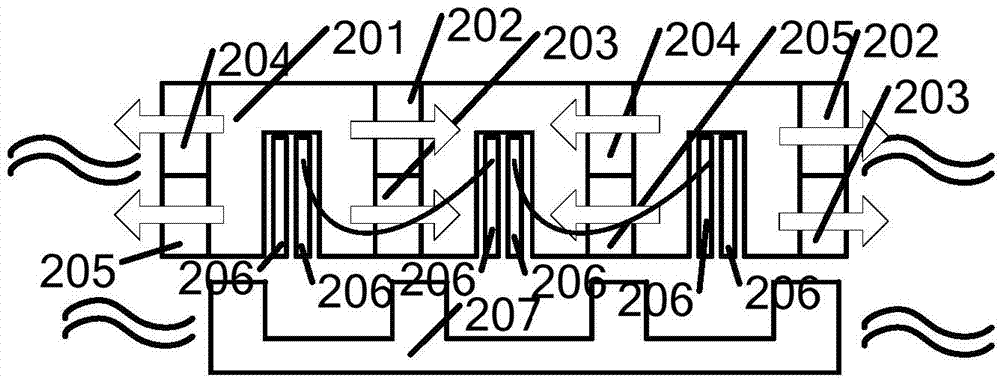
[0045] Install N35 N35 NdFeB permanent magnets with high magnetic energy product near the yoke of the U-shaped module of the linear motor stator (Z) 201, and close to the teeth of the U-shaped module of the linear motor stator (Z) 201 Install ferrite permanent magnets with low energy product grade Y30, and NdFeB permanent magnets with high magnetic energy product grades N35 and ferrite permanent magnets with low magnetic energy product grades Y30. Adhesive connection is A hybrid permanent magnet module is formed in one piece; a rare earth permanent magnet (Z) 202 with a clockwise magnetization direction and a clockwise ferrite permanent magnet with a clockwise magnetization direction are installed on one side of the U-shaped module of each linear motor stator (Z) 201 (Z) 203 is a hybrid permanent magnet module that is bonded and connected with glue, and on the other side of the U-shaped module of the linear motor stator (Z) 201, there is a rare earth permanent magnet (Z) 204 wh...


PUM


Abstract

The invention discloses an application method of mixed permanent magnets in a flux-switching permanent magnet motor, and relates to stator-core motors with permanent magnets. Rare-earth permanent magnets with high magnetic energy products are mounted at yoke positions of a stator module of the flux-switching permanent magnet motor. Ferrite permanent magnets with low magnetic energy products are mounted at tooth positions close to the motor stator module. The rare-earth permanent magnets with the high magnetic energy products and the ferrite permanent magnets with the low magnetic energy products are connected to be integrated into the mixed permanent magnets. The mixed permanent magnets with clockwise magnetization directions are mounted on one side of the motor stator module. The mixed permanent magnets with anticlockwise magnetization directions are mounted on the other side of the motor stator module. The mixed permanent magnets with the clockwise magnetization directions and the mixed permanent magnets with the anticlockwise magnetization directions are alternately mounted on two sides of the motor stator module. The defects of ultrahigh cost of existing flux-switching permanent magnet motors, serious magnetic saturation of teeth, reduction of motor torque density and large cogging torque are overcome.

Description

technical field [0001] The technical scheme of the invention relates to a motor with a stator core of permanent magnets, in particular to an application method of a hybrid permanent magnet in a magnetic flux switching permanent magnet motor. Background technique [0002] Since the permanent magnet of the flux switching permanent magnet motor is installed on the stator of the motor, and there is neither permanent magnet nor winding on the rotor, its structure is very stable, and it is a new type of permanent magnet motor with high fault tolerance. Compared with other stator-type permanent magnet synchronous motors, such as flux inversion permanent magnet motors and double salient pole permanent magnet synchronous motors, due to the special flux-gathering structure of the flux switching permanent magnet motors, it can generate High magnetic flux density, and the flux switching permanent magnet motor is a bipolar permanent magnet motor, which makes the effective flux utilizatio...

Claims


Application Information

Patent Timeline
Patent Type & Authority Applications(China)
IPC IPC(8): H02K1/17H02K1/14H02K1/02
Inventor 刘成成汪友华庞玲玲
Owner HEBEI UNIV OF TECH
Why Eureka
Try Eureka