Rotor of synchronous reluctance motor

A synchronous reluctance motor and rotor technology, applied in the direction of magnetic circuit rotating parts, magnetic circuit shape/style/structure, etc., can solve the problem that it is difficult to apply to high-power synchronous reluctance motors, and achieve easy guarantee of structural accuracy, The effect of convenient manufacturing and processing

Inactive Publication Date: 2014-12-24
HANGZHOU EASITECH
View PDF10 Cites 11 Cited by
  • Summary
  • Abstract
  • Description
  • Claims
  • Application Information

AI Technical Summary

Problems solved by technology

Such a structure is difficult to use in high-power synchronous reluctance motors, high-speed synchronous reluctance motors

Method used


Image

  • Rotor of synchronous reluctance motor
  • Rotor of synchronous reluctance motor
  • Rotor of synchronous reluctance motor

Examples


Embodiment Construction

[0041] The present invention will be further described below in conjunction with specific examples, but the present invention is not limited to these specific implementations. Those skilled in the art will realize that the present invention covers all alternatives, modifications and equivalents as may be included within the scope of the claims.

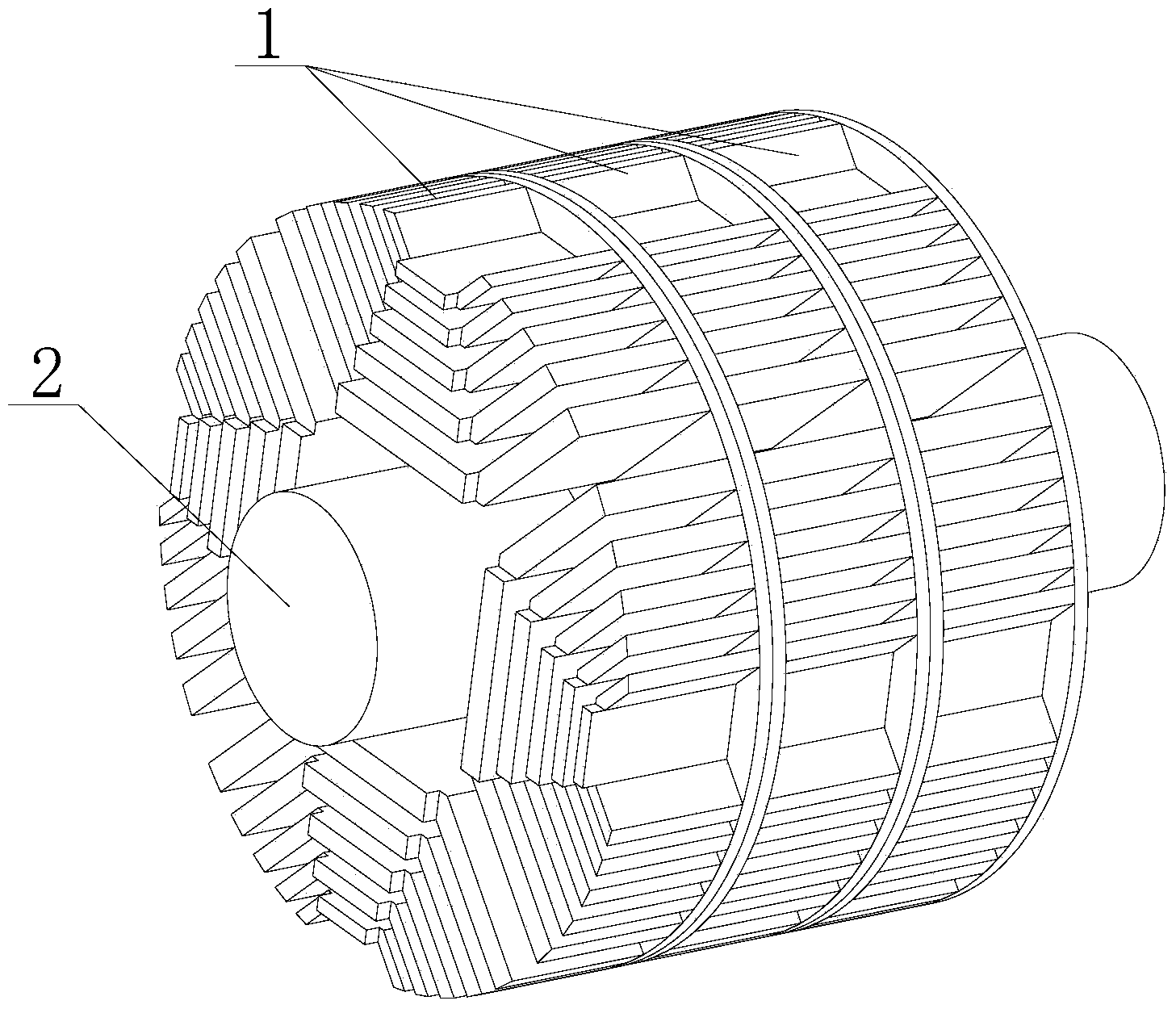
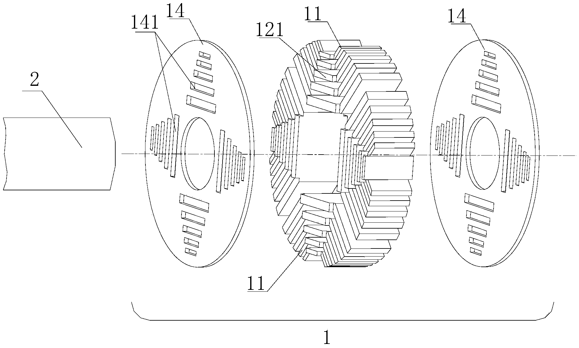
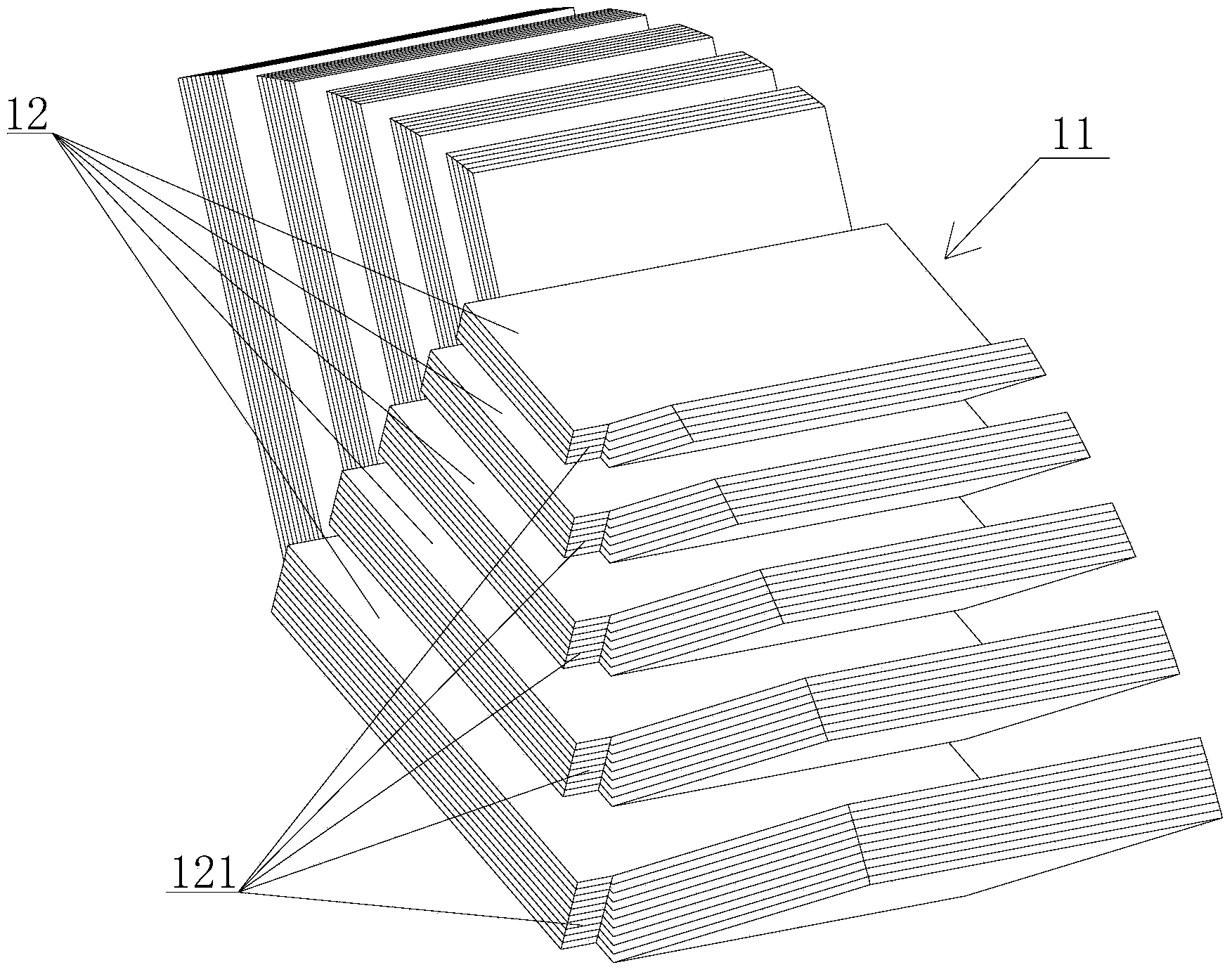
[0042] refer to Figure 1-8 , a synchronous reluctance motor rotor, including a plurality of rotor modules 1 arranged axially and sequentially staggered along a common axis, each rotor module 1 includes a plurality of magnetic poles 11, and the plurality of magnetic poles 11 are arranged in adjacent sections around the common axis Among them, each magnetic pole 11 includes a plurality of magnetic ribs 12 spaced apart in the radial direction, and each magnetic rib 12 is composed of a number of punching pieces 13, and positioning plates 14 are connected to both axial sides of the plurality of magnetic poles 11. The positioning plate 14...


PUM


Abstract

The invention provides a rotor of a synchronous reluctance motor. The rotor of the synchronous reluctance motor comprises multiple rotor modules which are arranged coaxially and staggered sequentially in the axial direction. Each rotor module comprises multiple magnetic poles, and the magnetic poles are arranged in adjacent sections around a common axis. Each magnetic pole comprises multiple magnetic ribs which are distributed in the radial direction at intervals. Each magnetic rib is composed of multiple punched sheets. Locating plates are connected to the two axial side faces of the magnetic poles. The locating plates are mounted on a rotating shaft in a sleeved mode. Bosses are arranged at the two axial ends of each magnetic rib respectively. Grooves are formed in the positions, corresponding to the bosses, of the locating plates. The axial end face of each magnetic pole is tightly attached to the axial end face of the corresponding locating plate in the mode that the bosses are inserted into the grooves. The magnetic poles and the locating plates of the rotor modules of the rotor are assembled through the matching between the bosses and the grooves, assembly is convenient to carry out, the magnetic poles are easy to locate, and position accuracy is high; the rotational inertia of the rotor is lower, manufacturing is easy and convenient to carry out, and the efficiency and the power factors of the motor are improved.

Description

technical field [0001] The invention relates to a synchronous reluctance motor rotor. Background technique [0002] A synchronous reluctance motor is a motor that relies on reluctance torque to operate. The reluctance torque is rooted in the rotor structure with unequal reluctance of the orthogonal and direct axes. The greater the difference between the reluctance of the orthogonal and direct axes, the greater the reluctance torque. In order to obtain the largest cross-direction axis reluctance difference, the thinnest magnetic bridge is required in the structure, and it is best to have no magnetic bridge. After the magnetic bridge is thinned, the stiffness of the rotor is reduced, and the stress concentration at the position of the magnetic bridge causes insufficient strength. This situation is more prominent in the high-power synchronous reluctance motor. It is necessary to design a suitable structure to solve these problems. [0003] Patent Nos. CN101443982A, CN1881757A,...

Claims


Application Information

Patent Timeline
Patent Type & Authority Applications(China)
IPC IPC(8): H02K1/22H02K1/28
Inventor 晋兆海方卫中洪涛朱彤华
Owner HANGZHOU EASITECH
Why Eureka
Try Eureka