Charged body electric removal device, and charged body electric removal method utilizing same device
A technology of a charged body and an electrification method, which is applied in the field of electrified body static elimination devices, can solve problems such as obstacles in the treatment of resin molded products, and achieve the effects of rapid static elimination treatment, simplified structure, and reduced ozone generation.
- Summary
- Abstract
- Description
- Claims
- Application Information
AI Technical Summary
Problems solved by technology
Method used
Image
Examples
no. 1 Embodiment approach
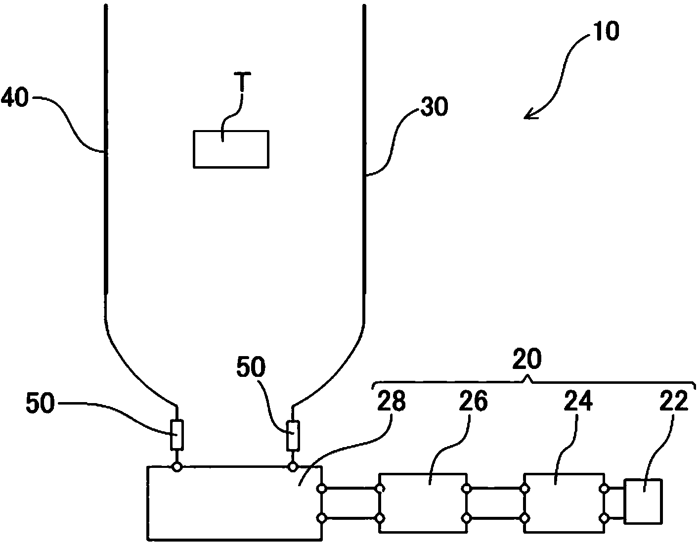
[0036] figure 1 It is a schematic configuration diagram of the charged object static elimination device of the first embodiment.
[0037] The charged body static elimination device 10 of the present embodiment is provided with: a power supply device 20; and a positive electrode 30 and a negative electrode 40, which are composed of linear bodies arranged in parallel at a required interval. The positive electrode 30 and the negative electrode 40 are electrically connected to the power supply device 20 , respectively. In addition, the separation distance between the positive electrode 30 and the negative electrode 40 can be appropriately set according to the charged body T to be subjected to the static elimination treatment or the size of the charged body T and a transport member (not shown) for transporting the charged body T.
[0038] Such as figure 1 As shown, the power supply device 20 of this embodiment is constituted by sequentially electrically connecting the power sup...
no. 2 Embodiment approach
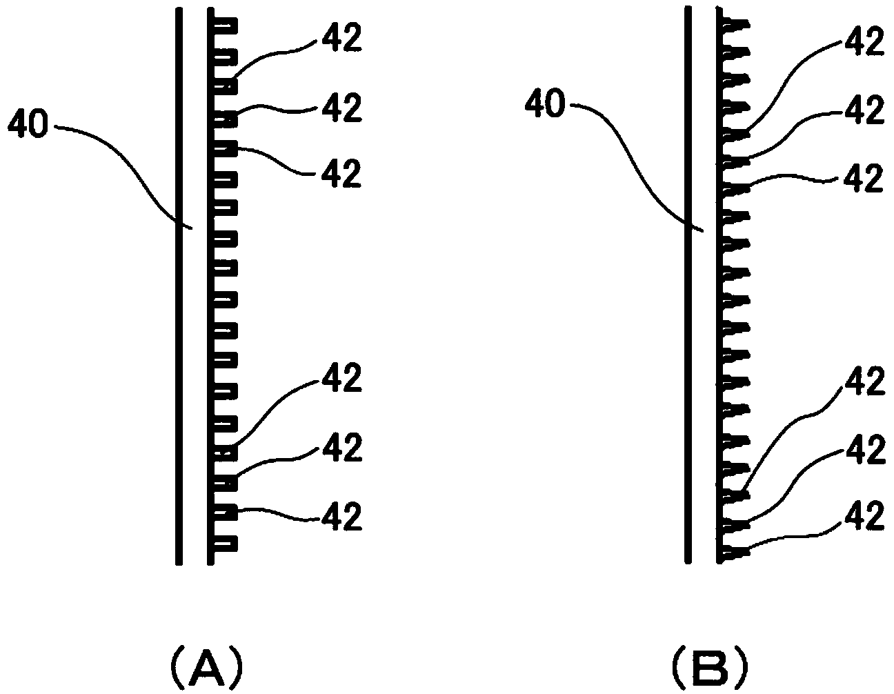
[0051] figure 2 (A) and figure 2 (B) is an enlarged front view showing a modified example of the negative electrode. The present embodiment is characterized in that the protruding body 42 protruding toward the positive electrode 30 side is arranged on the surface of the linear body forming the negative electrode 40 . Since other configurations can be the same as those of the first embodiment, detailed descriptions are omitted here.
[0052] By arranging such protrusions 42 , corona discharge between the negative electrode 40 and the electrified body T can be easily generated. Such as figure 2 (A) and figure 2 As shown in (B), a plurality of protrusions 42 are arranged at required intervals along the extending direction of the negative electrode 40 (linear body), but the number of protrusions 42 may be only one.
[0053] The protrusion 42 arranged on the surface of the negative electrode 40 may be formed as figure 2 The columnar body shown in (A) can also be formed a...
no. 3 Embodiment approach
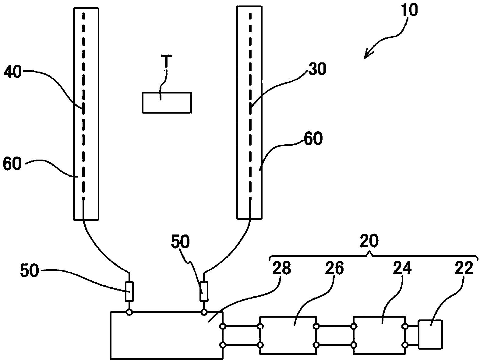
[0056] image 3 It is a schematic configuration diagram of a charged body static elimination device according to a third embodiment. Figure 4 yes image 3 A top view of the electrode part.
[0057] The present embodiment is characterized in that shields 60 formed in a U-shape in plan view are disposed on the outer portions of the positive electrode 30 and the negative electrode 40 . The shield 60 is formed of an insulator such as synthetic resin.
[0058] At the positive electrode 30 and the negative electrode 40, shields 60 for preventing electric field leakage are arranged on the outer positions on the opposite side to the other electrode (the negative electrode 40 or the positive electrode 30), respectively, because the opening 62 of the shield 60 Since they are arranged in a state facing each other, the electric field formed by the positive electrode 30 and the negative electrode 40 can be prevented from leaking to the outside of the charged body static eliminator 10 ....
PUM
 Abstract
Description
Claims
Application Information
 - R&D
- Intellectual Property
- Life Sciences
- Materials
- Tech Scout
- Unparalleled Data Quality
- Higher Quality Content
- 60% Fewer Hallucinations
Browse by: Latest US Patents, China's latest patents, Technical Efficacy Thesaurus, Application Domain, Technology Topic, Popular Technical Reports.
© 2025 PatSnap. All rights reserved.Legal|Privacy policy|Modern Slavery Act Transparency Statement|Sitemap|About US| Contact US: help@patsnap.com


