Charged body static elimination device and charged body static removal method using the device

A technology of electrified body and electrified method, which is applied in the field of electrified body de-static device, can solve problems such as processing obstacles of resin molded products, and achieve the effects of rapid de-static treatment, reduction of ozone generation, and reduction of production volume

Active Publication Date: 2016-10-19
HARMO
View PDF8 Cites 0 Cited by
  • Summary
  • Abstract
  • Description
  • Claims
  • Application Information

AI Technical Summary

Problems solved by technology

When the charged resin molded product is to be transported by a transport robot, etc., the resin molded product may adhere to the arm (gripper) of the transport robot due to static electricity and cannot be separated from the arm. Therefore, there are obstacles in the handling of resin molded products

Method used


Image

  • Charged body static elimination device and charged body static removal method using the device
  • Charged body static elimination device and charged body static removal method using the device
  • Charged body static elimination device and charged body static removal method using the device

Examples


no. 1 Embodiment approach

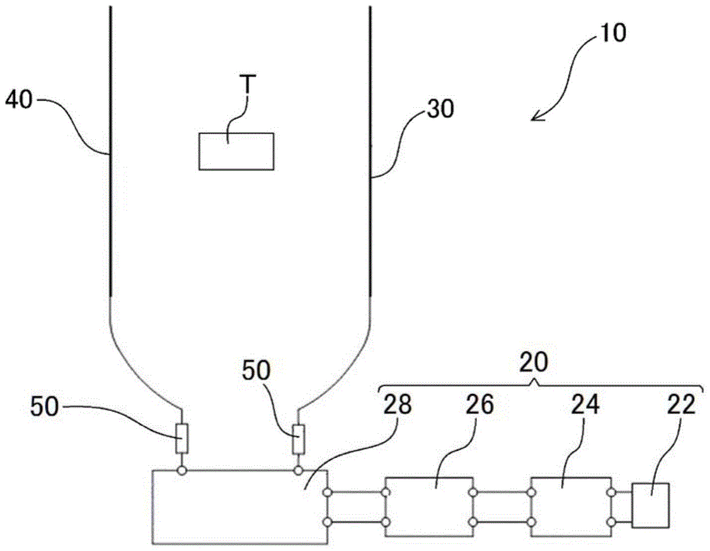
[0036] figure 1 It is a schematic block diagram of the charged body static elimination apparatus of 1st Embodiment.

[0037] The charged body static elimination apparatus 10 of this embodiment is equipped with the power supply apparatus 20, and the positive electrode 30 and the negative electrode 40, and these are comprised by the linear body arrange|positioned in parallel with a predetermined space|interval. The positive electrode 30 and the negative electrode 40 are respectively electrically connected to the power supply device 20 . In addition, the separation distance between the positive electrode 30 and the negative electrode 40 can be appropriately set according to the charged body T to be subjected to the static elimination treatment or the charged body T and the size of the transport member (not shown) that transports the charged body T.

[0038] like figure 1 As shown, the power supply device 20 of the present embodiment is configured by electrically connecting th...

no. 2 Embodiment approach

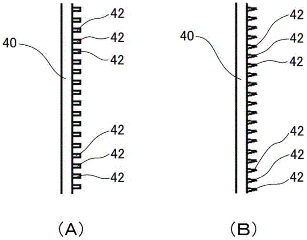
[0051] figure 2 (A) and figure 2 (B) is an enlarged front view showing a modified example of the negative electrode. The present embodiment is characterized in that the protruding body 42 protruding toward the positive electrode 30 side is arranged on the surface of the linear body forming the negative electrode 40 . Since other configurations can be the same as those of the first embodiment, detailed descriptions are omitted here.

[0052] By arranging such protrusions 42 , corona discharge between the negative electrode 40 and the electrified body T can be easily generated. like figure 2 (A) and figure 2 As shown in (B), a plurality of protrusions 42 are arranged at required intervals along the extending direction of the negative electrode 40 (linear body), but the number of protrusions 42 may be only one.

[0053] The protrusion 42 arranged on the surface of the negative electrode 40 may be formed as figure 2 The columnar body shown in (A) can also be formed as ...

no. 3 Embodiment approach

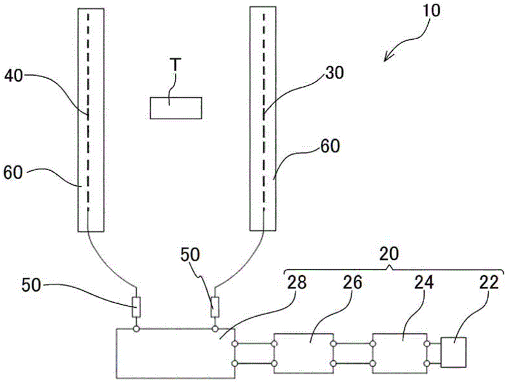
[0056] image 3 It is a schematic configuration diagram of a charged body static elimination device according to a third embodiment. Figure 4 Yes image 3 A top view of the electrode part.

[0057] The present embodiment is characterized in that shields 60 formed in a U-shape in plan view are disposed on the outer portions of the positive electrode 30 and the negative electrode 40 . The shield 60 is formed of an insulator such as synthetic resin.

[0058] At the positive electrode 30 and the negative electrode 40, shields 60 for preventing electric field leakage are arranged on the outer positions on the opposite side to the other electrode (the negative electrode 40 or the positive electrode 30), respectively, because the opening 62 of the shield 60 Since they are arranged in a state facing each other, the electric field formed by the positive electrode 30 and the negative electrode 40 can be prevented from leaking to the outside of the charged body static eliminator 10 ....


PUM


Abstract

The present invention provides a charged body electric removal device, and a charged body electric removal method utilizing the same device. The device generates a corona to be discharged to consume the electrostatic energy on the charged body, and enables electric removal processing on the charged body. The device is characterized by comprising a power supply unit (20), a positive electrode (30) and a negative electrode (40). The two electrodes are electrically connected to the power supply unit (20). The positive electrode (30) and the negative electrode (40) are parallelly disposed at a needed interval. The positive electrode (30) and the negative electrode (40) are formed by threadlike bodies having identical voltages when the coronas at the positive electrode (30) and the negative electrode (40) are discharged. The voltages supplied to the positive electrode (30) and the negative electrode (40) are maintained in the scope of being greater than the threshold voltage when the positive electrode (30) and the negative electrode (40) start to be discharged.

Description

technical field [0001] The present invention relates to an apparatus for removing static electricity from a charged body and a method for removing static electricity from a charged body using the same. Background technique [0002] In many cases, a resin molded article molded by a resin molding apparatus is in a charged state due to static electricity generated by contact with an article made of another material. When a resin molded product in such an electrified state is to be conveyed by a conveying robot or the like, the resin molded product may adhere to the arm portion (clamp portion) of the conveying robot due to static electricity and cannot be separated from the arm portion. Therefore, there is an obstacle in the handling of the resin molded product. [0003] In order to solve such a problem, for example, Patent Document 1 proposes a configuration involving a device in which air ions are blown to an object to be neutralized in a charged state, and the static electri...

Claims


Application Information

Patent Timeline
Patent Type & Authority Patents(China)
IPC IPC(8): H05F3/04
Inventor 涩谷弘树
Owner HARMO
Why Eureka
Try Eureka