Seat device

A technology of a seat and a pressure-sensitive switch, applied in the field of seat devices, can solve the problems of being different, unable to properly detect the load, complex structure of the seat device, etc., and achieve the effect of a simple structure

Active Publication Date: 2017-11-14
FUJIKURA LTD
View PDF10 Cites 0 Cited by
  • Summary
  • Abstract
  • Description
  • Claims
  • Application Information

AI Technical Summary

Problems solved by technology

[0008] However, in the seat device of the aforementioned Patent Document 1, since seat occupancy sensors having different structures are required, there is a problem that the structure of the seat device becomes complicated.
Furthermore, in the seat device of Patent Document 1, when different cushion pads are used, there is also a problem that the load may not be properly detected depending on the specific cushion pad.

Method used


Image

  • Seat device
  • Seat device
  • Seat device

Examples


no. 2 Embodiment approach

[0117] Next, a preferred second embodiment of the seat device according to the present invention will be described in detail with reference to the drawings. Among the constituent elements of the seat device of the second embodiment, the same or equivalent constituent elements as those of the first embodiment are denoted by the same reference numerals, and overlapping descriptions are appropriately omitted.

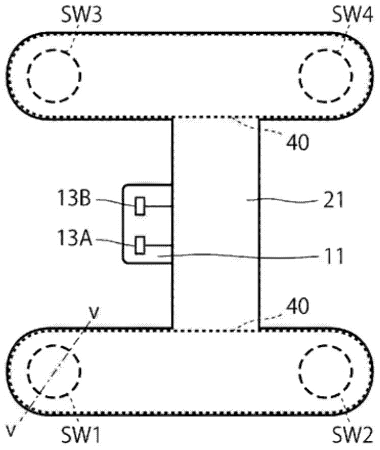
[0118] Figure 12 It is a figure which shows the seating sensor in 2nd Embodiment. Such as Figure 12 As shown, the seat device in this embodiment includes a seating sensor 70 as a component instead of the seating sensor 2 of the first embodiment.

[0119] Specifically, the seat occupancy sensor 70 has a structure in which the first sensor unit 71 and the second sensor unit 72 are electrically and mechanically connected by a cable 73 .

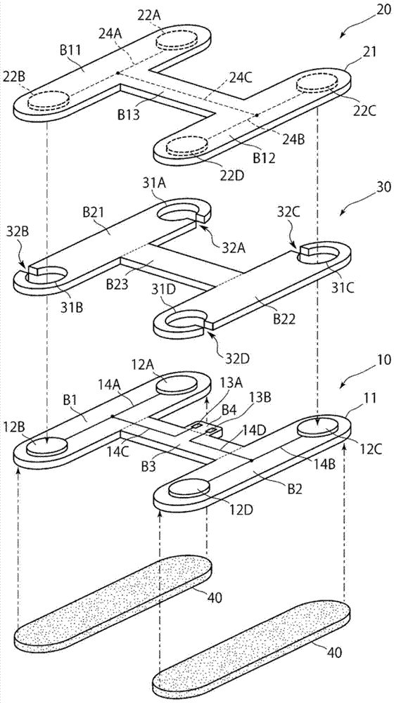
[0120] In the first sensor section 71, the figure 2 The shown main block B1 portion of the first insulating plate 11, the main block...

no. 3 Embodiment approach

[0140] Next, a preferred third embodiment of the seat device of the present invention will be described in detail with reference to the drawings. Among the constituent elements of the seat device according to the third embodiment, the same or equivalent constituent elements as those in the above-mentioned embodiment are denoted by the same reference numerals, and overlapping descriptions are appropriately omitted.

[0141] The seat device in the third embodiment differs from the seat device 1 in the first embodiment in that a mounting member different from the seat base 4 is included as a component.

[0142] Fig. 16(A) and Fig. 16(B) are diagrams showing a mounting member of the third embodiment. As shown in FIG. 16(A) and FIG. 16(B), the mounting member of this embodiment has a seat frame 91 and a plurality of springs 92 .

[0143] The seat frame 91 is formed into a frame structure including a front frame member 91a arranged as a frame of a front part, a rear frame member 91...


PUM


Abstract

To provide a seat device capable of properly detecting sitting even if the sitting position changes in the front-rear direction with a simpler structure. A seat device (1) of the present invention includes a cushion pad (3) and a pressure-sensitive switch (SW1) for detecting a load applied from a seat surface of the cushion pad (3). The lower surface of the cushion pad (3) in this seat device (1) is formed with a groove (50) extending along the front and rear direction of the cushion pad (3), and a pressure sensitive device is arranged in the space of the groove (50). switch (SW1).

Description

technical field [0001] The present invention relates to a seat device of a vehicle and the like, and is a preferable device in the technical field of detecting seating. Background technique [0002] As a safety system of a vehicle, an alarm system that warns of not wearing a seat belt while riding in a vehicle has been put into practical use. In this alarm system, a warning is issued when it is detected that a person is seated but not wearing a seat belt. As a seat device used in such an alarm system and the like, a device disclosed in Patent Document 1 below has been proposed. [0003] The seat device of this Patent Document 1 includes a cushion pad and a cushion frame on which the cushion pad is placed, and two types of seating sensors are provided between the cushion pad and the cushion frame. [0004] The first seat occupancy sensor is disposed at the center of the seating area between the cushion pad and the cushion frame, and includes a push-button switch and a press...

Claims


Application Information

Patent Timeline
Patent Type & Authority Patents(China)
IPC IPC(8): B60N2/44A47C7/02A47C7/62B60N2/90
CPCB60N2/002B60N2/70
Inventor 中崎滋
Owner FUJIKURA LTD
Why Eureka
Try Eureka