Abnormality judging device, abnormality judging method, and recording medium

A technology for abnormality determination and abnormality, which is applied in image analysis, image enhancement, instrumentation, etc., and can solve problems such as inability to perform smoothing

Inactive Publication Date: 2020-11-10
SHARP KK
View PDF7 Cites 0 Cited by
  • Summary
  • Abstract
  • Description
  • Claims
  • Application Information

AI Technical Summary

Problems solved by technology

[0007] However, the invention described in Patent Document 1 has a problem that appropriate smoothing cannot be performed depending on the type of foreign matter because the least square method is used to generate flattened data.

Method used


Image

  • Abnormality judging device, abnormality judging method, and recording medium
  • Abnormality judging device, abnormality judging method, and recording medium
  • Abnormality judging device, abnormality judging method, and recording medium

Examples


Embodiment approach 1

[0021] Hereinafter, for one embodiment of the present invention, use Figure 1 to Figure 6 Describe in detail.

[0022] (Structure of Abnormality Judgment Device)

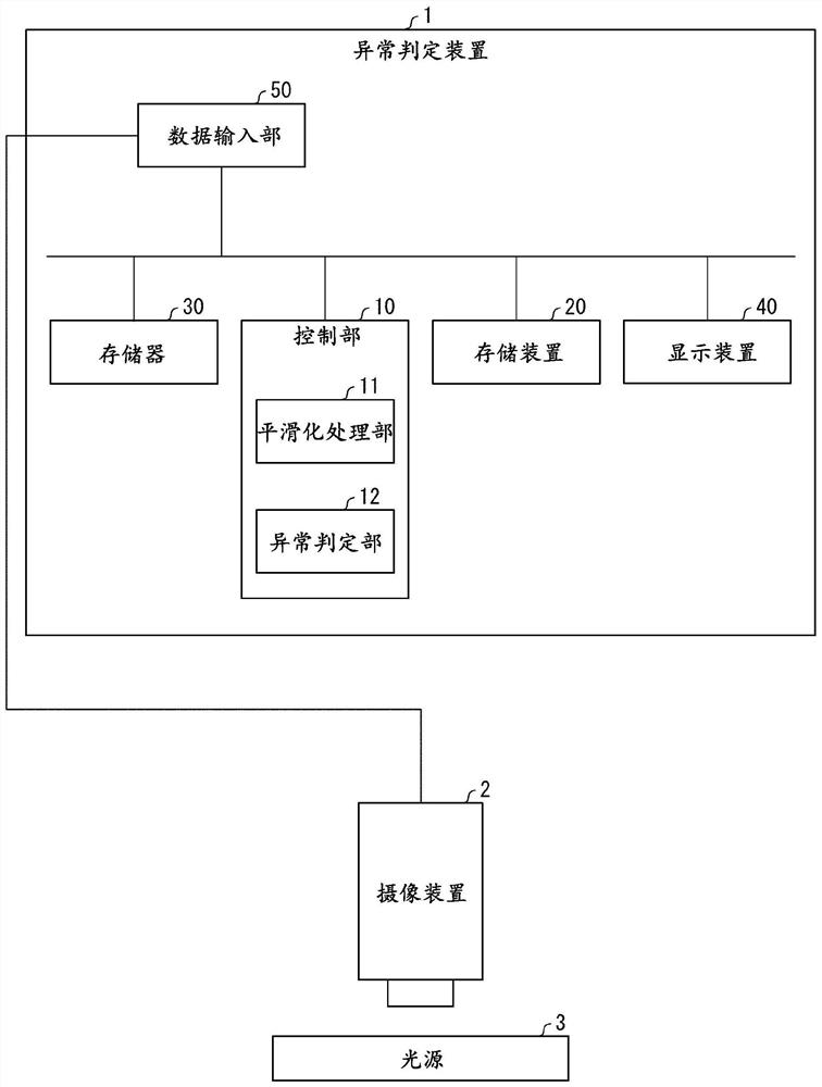
[0023] Regarding the configuration of the abnormality judging device 1 according to the present embodiment, using figure 1 Be explained. figure 1 It is a block diagram showing an example of the configuration of main parts of the abnormality determination device 1 .

[0024] The abnormality determination device 1 determines whether or not the imaging device 2 is abnormal based on imaging data obtained by imaging the light source 3 , which is an object with uniform brightness, by the imaging device 2 . According to the illustrated example, the abnormality determination device 1 includes a control unit 10 , a storage device 20 , a memory 30 , a display device 40 , and a data input unit 50 . The control unit 10 includes a smoothing processing unit 11 and an abnormality determination unit 12 .

[0025] The control u...


PUM


Abstract

The present invention provides an abnormality determination device capable of appropriately detecting the presence or absence of an abnormality in an imaging device. The abnormality judging device (1) of the present invention judges whether there is an abnormality in the imaging device (2) based on the imaging data of an object (light source 3) with uniform brightness. The luminance data obtained by extracting luminance information from the imaging data is divided into a plurality of areas, and a smoothing filter is used for each predetermined area, and the smoothing filter is positioned at a position smaller than the predetermined area. moving within a range to generate smooth image data; an abnormality judging unit (12) compares the smoothed image data and the segmented data to judge whether or not the imaging device is abnormal.

Description

technical field [0001] The present invention relates to an abnormality determination device and the like for detecting a defective product in an inspection of an imaging device. Background technique [0002] There is known a technique for inspecting whether or not the imaging device is a defective product by detecting foreign matter or the like mixed in at the manufacturing stage of the imaging device using an image captured by the imaging device. For example, Patent Document 1 discloses an inspection device that compares an n-order fitting curve generated by applying the least squares method to digital source image data with the digital source image data to determine whether there is a foreign object, and to check whether the imaging device is faulty or not. Good product, the digital source image data is obtained by photographing the reference plane of the inspected object. [0003] prior art literature [0004] patent documents [0005] Patent Document 1: Japanese Unexa...

Claims


Application Information

Patent Timeline
Patent Type & Authority Patents(China)
IPC IPC(8): H04N17/00
CPCG06T7/0002G06T2207/20021G06T2207/30168H04N25/68G06T5/002G06T7/11G06T3/4007G06T7/40
Inventor 石井康史
Owner SHARP KK
Why Eureka
Try Eureka