Abnormality sensing apparatus, abnormality sensing method, and abnormality sensing program

A detection method and anomaly detection technology, applied in the direction of measuring devices, measuring electricity, measuring electrical variables, etc., can solve the problems of not keeping fault data and difficult to use abnormal detection of equipment status

Active Publication Date: 2021-01-26
MITSUBISHI ELECTRIC CORP
View PDF9 Cites 0 Cited by
  • Summary
  • Abstract
  • Description
  • Claims
  • Application Information

AI Technical Summary

Problems solved by technology

However, long-lived equipment such as generators and elevators are mostly maintained before failure, so in many cases, manufacturers, maintenance operators, and equipment introducers (users) do not keep failure data
Therefore, it is difficult to detect abnormalities by learning the state of the equipment at the time of failure and the fluctuation of measurement data in advance.

Method used


Image

  • Abnormality sensing apparatus, abnormality sensing method, and abnormality sensing program
  • Abnormality sensing apparatus, abnormality sensing method, and abnormality sensing program
  • Abnormality sensing apparatus, abnormality sensing method, and abnormality sensing program

Examples


Embodiment approach 1

[0039] ***Description of structure***

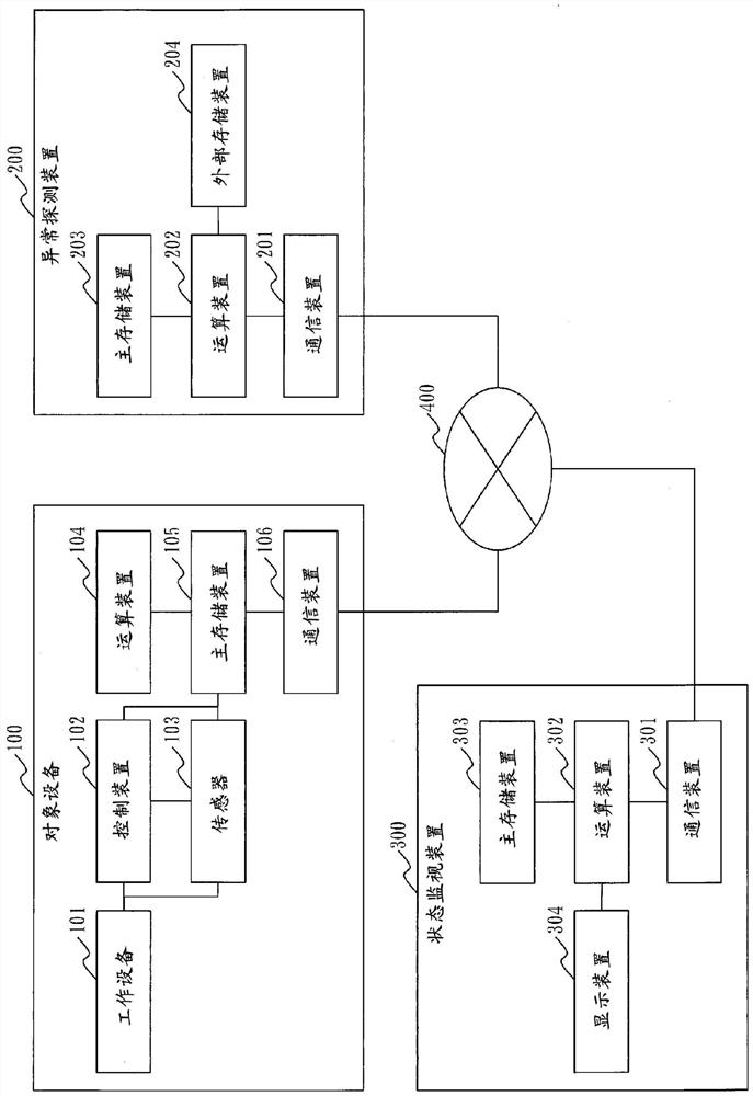
[0040] refer to figure 1 , and the hardware configuration of the abnormality detection system 1 according to Embodiment 1 will be described.

[0041] The abnormality detection system 1 includes a target device 100 , an abnormality detection device 200 , and a state monitoring device 300 . The target device 100, the abnormality detection device 200, and the status monitoring device 300 are connected via a network 400 such as a LAN (Local Area Network). The abnormality detection device 200 and the state monitoring device 300 may be a server with a physical entity or may be constituted by a cloud. Network 400 may also be a virtual network.

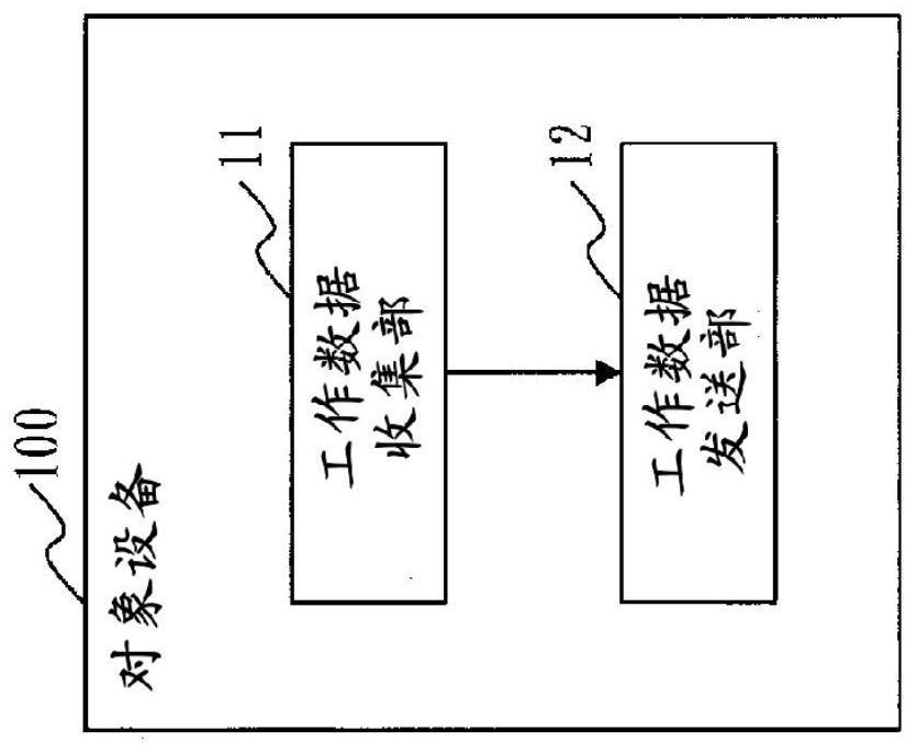
[0042] The target device 100 is a device to be targeted for abnormality detection.

[0043] The target device 100 includes hardware such as an operating device 101 , a control device 102 , a sensor 103 , an arithmetic device 104 , a main storage device 105 , and a communication device 106 .

[0044...

Deformed example 1

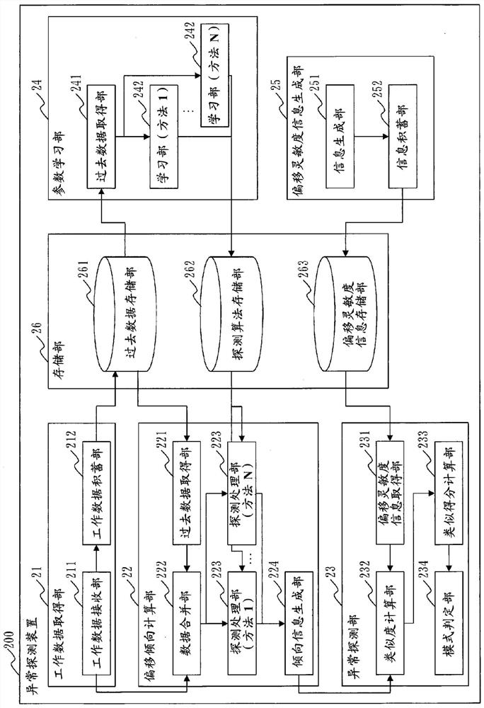
[0147] In Embodiment 1, the operation data collection unit 11, the operation data transmission unit 12, the operation data acquisition unit 21, the deviation tendency calculation unit 22, the abnormality detection unit 23, the parameter learning unit 24, the deviation sensitivity information generation unit 25, the result The functions of each part of the receiving unit 31 and the result output unit 32 are realized by software. However, as Modification 1, the functions of the above-mentioned components may also be realized by hardware. Regarding this Modification 1, points different from Embodiment 1 will be described.

[0148] refer to Figure 15 , the hardware configuration of the abnormality detection system 1 according to Modification 1 will be described.

[0149] In the case where the functions of the above-mentioned respective parts are realized by hardware, the target device 100 includes an electronic circuit 107 instead of the computing device 104 and the main storag...

Deformed example 2

[0154]As Modification 2, some functional constituent elements may be realized by hardware, and other functional constituent elements may be realized by software.

[0155] The computing devices 104, 202, and 302, the main storage devices 105, 203, and 303, and the electronic circuits 107, 205, and 305 are called processing circuits. That is, the functions of the above-mentioned parts are realized by the processing circuit.


PUM


Abstract

A deviation trend calculation unit (22) specifies data which deviate from other data from among object data, calculates a deviation score using evaluation data obtained from an object device as inputthrough use of each of a plurality of deviation value sensing methods for calculating a deviation score indicating the degree of deviation of specified data, and calculates deviation trend informationfrom the calculated deviation score. An abnormality sensing unit (23) calculates the degree of similarity between deviation sensitivity information indicating sensitivity to each of a plurality of abnormality patterns for each of the plurality of deviation value sensing methods and the calculated deviation trend information, for each abnormality pattern, and senses an abnormality in an object device.

Description

technical field [0001] The present invention relates to a technique for detecting an abnormality of a target device based on data obtained from the target device. Background technique [0002] In the field of preventive maintenance and equipment maintenance, technology development for detecting or predicting signs of deterioration and failure of equipment is carried out in order to reduce maintenance implementation and spare parts management to the necessary minimum without waste. In the process of focusing on sensor networks and big data analysis, technologies are being developed to sense the working conditions of equipment and perform abnormal detection or fault prediction based on physical analysis or statistical prediction. [0003] For the abnormal detection of equipment, the following method is adopted in most cases: collect the working data of the equipment, and build an abnormal detection model on the basis of grasping the characteristics of the normal and abnormal d...

Claims


Application Information

Patent Timeline
Patent Type & Authority Applications(China)
IPC IPC(8): G01M99/00G05B23/02
CPCG06F17/18G05B23/0283G05B23/024G05B23/0281G01M99/008G01R31/00G05B23/0237G06F18/28G06F18/2433G06F18/2193G06F18/10G06F18/22
Inventor 竹内智晴
Owner MITSUBISHI ELECTRIC CORP
Why Eureka
Try Eureka