Machine for cleaning needle holder plates for knitting machines

A needle box board, knitting machine technology, applied in the direction of cleaning methods and utensils, cleaning methods using liquids, knitting, etc., can solve the problems of ultrasonic machine influence, unsatisfactory cleaning results, etc.

Active Publication Date: 2014-12-24
马尔切洛·加廖托
View PDF7 Cites 3 Cited by
  • Summary
  • Abstract
  • Description
  • Claims
  • Application Information

AI Technical Summary

Problems solved by technology

[0012] But these machines also often require the needle box plate to be completely removed, and in particular all needles and all actuator rods; sometimes, these machines can be operated without the needle box plate completely removed, but in these cases the cleani...

Method used


Image

  • Machine for cleaning needle holder plates for knitting machines
  • Machine for cleaning needle holder plates for knitting machines
  • Machine for cleaning needle holder plates for knitting machines

Examples


Embodiment Construction

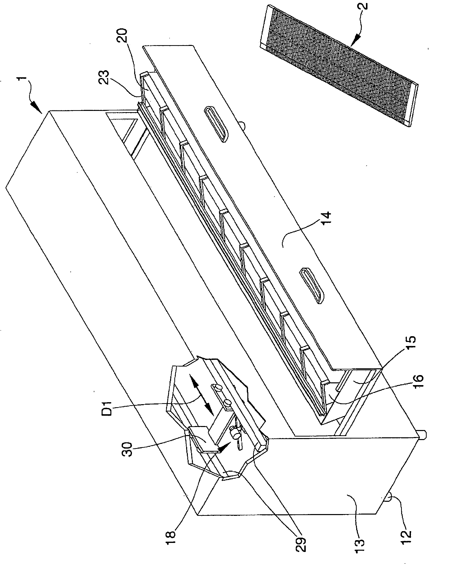
[0032] With particular reference to the accompanying drawings, a machine for cleaning a needle box plate for a knitting machine is indicated generally by 1 .

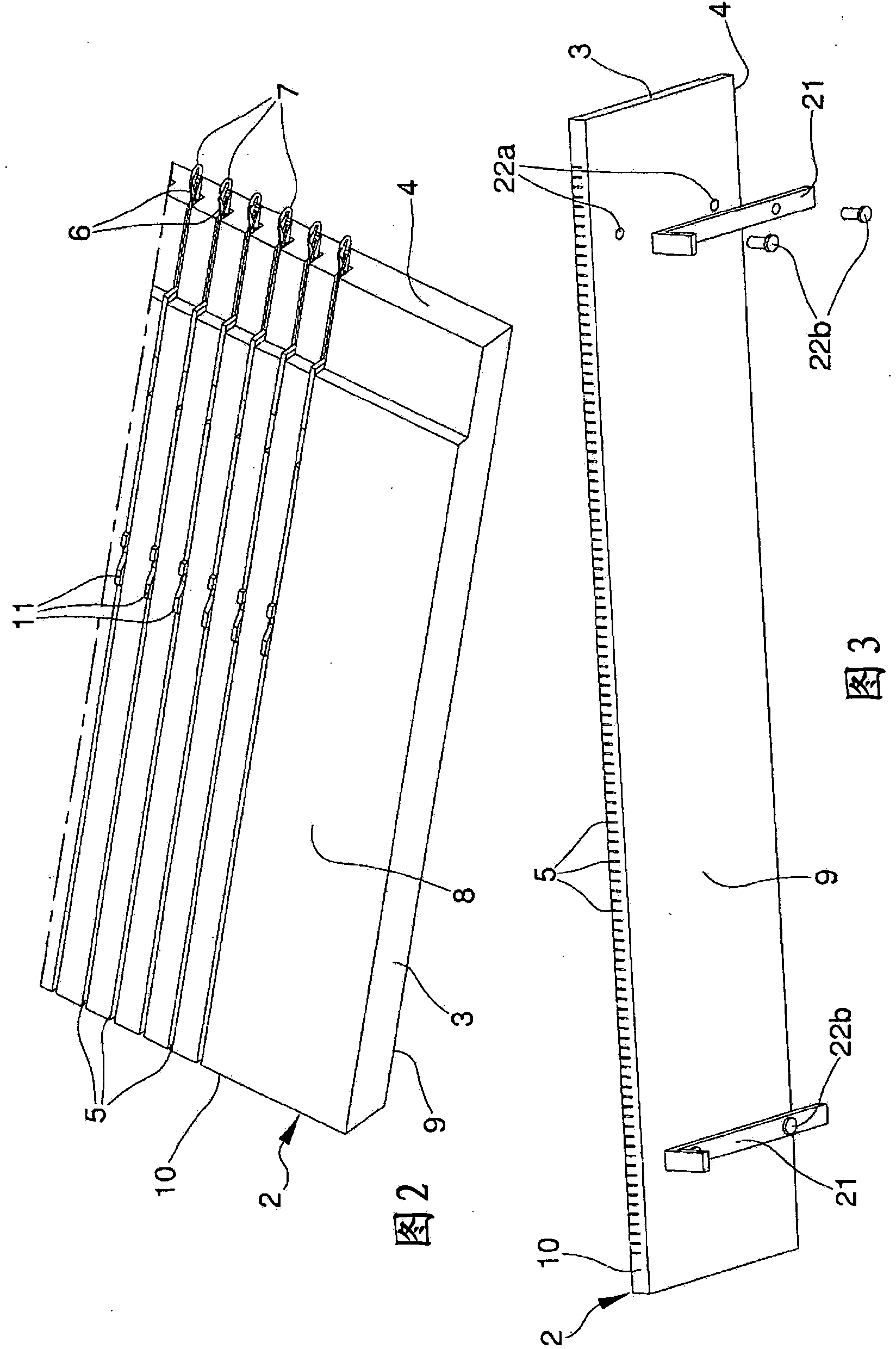
[0033] The machine 1 is especially intended for cleaning one or more needle cassette plates or needle beds 2 comprising:

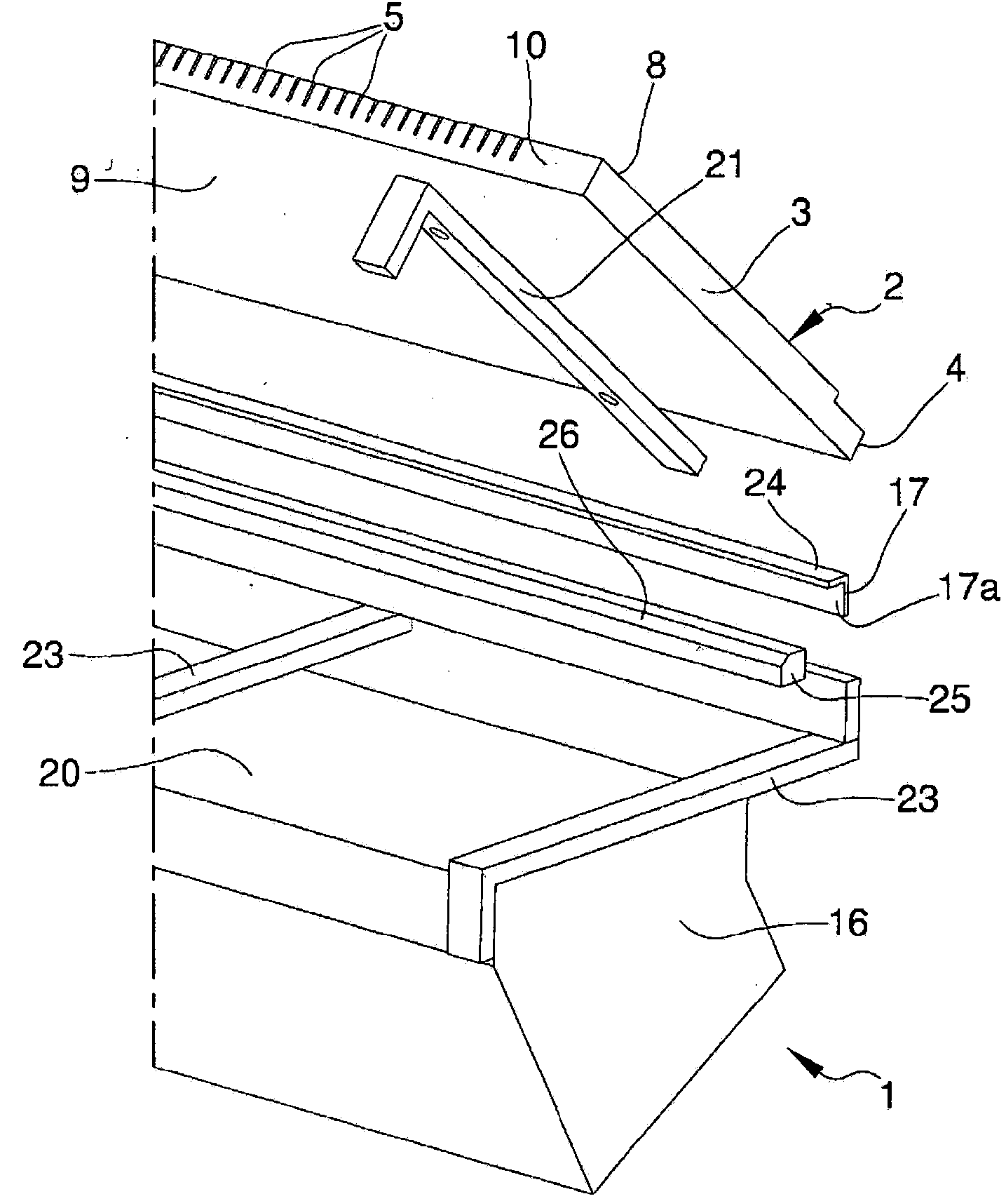
[0034] - at least a holding plate-like body 3 having a substantially rectilinear working side 4 and a plurality of slots 5 substantially transverse to the working side 4; and

[0035] - A plurality of needles 6 for knitwear slidably housed in the groove 5 and having at least a working end 7 protruding from the working side 4 .

[0036] In more detail, the plate-like body 3 has a first main face 8 and a second main face 9 facing each other.

[0037] The grooves 5 are obtained on the first main face 8 and are all perpendicular to the working side 4 .

[0038] The slot 5 extends from the working side 4 to the opposite side 10 substantially along the entire width of the plate-like body 3 .

[0039] I...


PUM


Abstract

The machine (1) for cleaning needle holder plates for knitting machines comprises: -a base frame (12); -a washing tank (15), assembled on the base frame (12); -a supporting device (16) which can be placed in correspondence to said washing tank (15) and suitable for supporting, in a preset washing position, at least a needle holder plate (2) for knitting machines, the needle holder plate (2) comprising: -a plate-shaped body (3) having a work side (4) substantially rectilinear and a plurality of grooves (5) substantially transversal to the work side (4); and -a plurality of needles (6) for knitwear, housed sliding in the grooves (5) and having a work extremity (7) which protrudes overhanging from the work side (4); and -dispensing means (18) associated with the base frame (12) and suitable for dispensing a washing fluid (19) under pressure towards the needle holder plate (2) placed in the preset washing position.

Description

technical field [0001] The invention relates to a machine for cleaning a needle box plate for a knitting machine. Background technique [0002] Knitting machines are known to be automatic, having a plurality of moving needles for the stitches of one or more yarns to be wound. The needles are usually assembled on a cassette plate called a "needle bed", which has a holding shape and a series of slots. [0003] The needles are received in a sliding manner along an equal number of parallel slots and protrude from the side of the needle box plate defining the working side along which the yarn runs during the trial. [0004] Within said slots, one or more actuating rods called "sub-needles", "sinks" and "sockets" are also arranged in a sliding manner, the purpose of which is to depend on the type of knitting work to be performed on the yarn and move the needle. [0005] During the use of the knitting machine, the needle box plate tends to become very dirty, not only due to dust...

Claims


Application Information

Patent Timeline
IPC IPC(8): D04B37/02
CPCB08B3/024D04B37/02
Inventor 马尔切洛·加廖托
Owner 马尔切洛·加廖托
Why Eureka
Try Eureka