
Method for running communication device

A communication device, a technology of ring communication, applied in the direction of data exchange through path configuration, digital transmission system, electrical components, etc., can solve the problems of errors, difficult to develop data transmission, etc., and achieve the effect of simple cost

Inactive Publication Date: 2014-12-31
ROBERT BOSCH GMBH
View PDF5 Cites 0 Cited by
  • Summary
  • Abstract
  • Description
  • Claims
  • Application Information

AI Technical Summary

Problems solved by technology

In addition, only the send signal is transmitted synchronously with the clock signal, whereas the phase-synchronous transmission of the receive signal can become more and more difficult to develop due to internal delay times in the slave at high data rates and can cause errors in the data transmission

Method used


Image

  • Method for running communication device
  • Method for running communication device

Examples


Embodiment Construction

[0021] The invention is shown schematically in the drawing on the basis of an embodiment and will be described in more detail below with reference to the drawing.

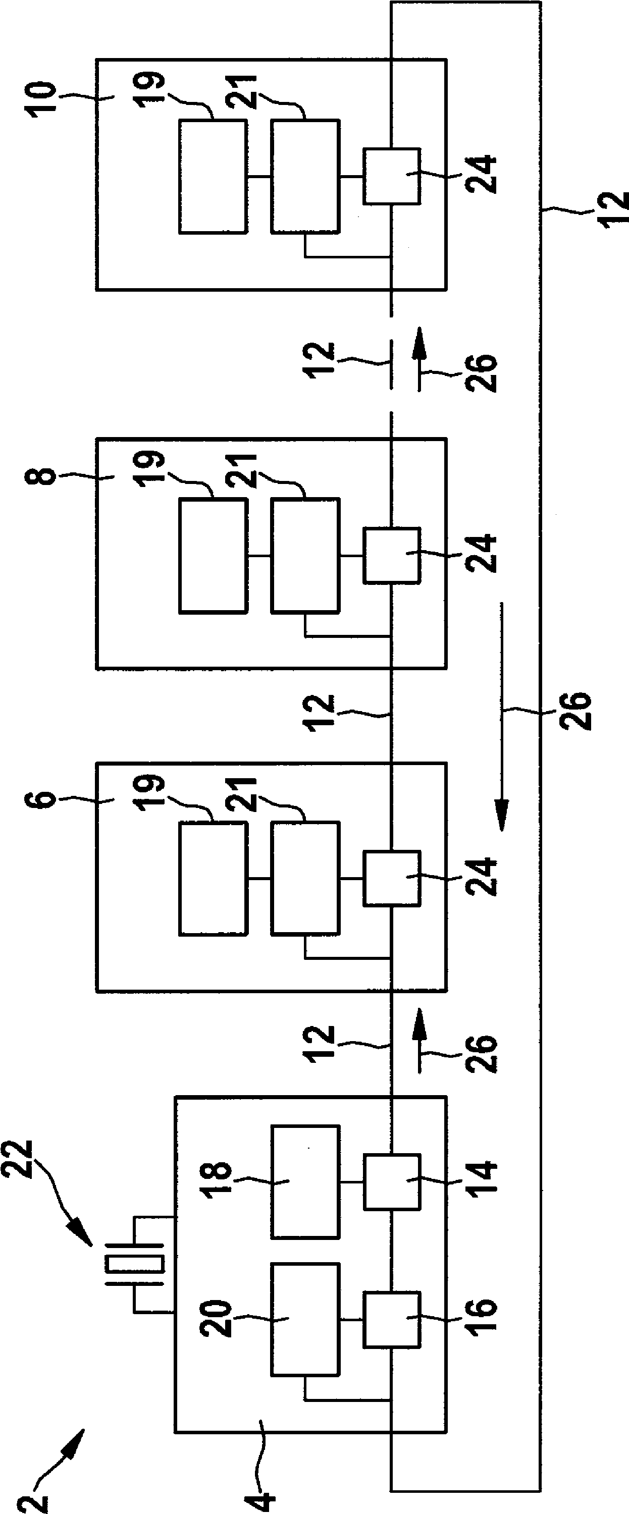
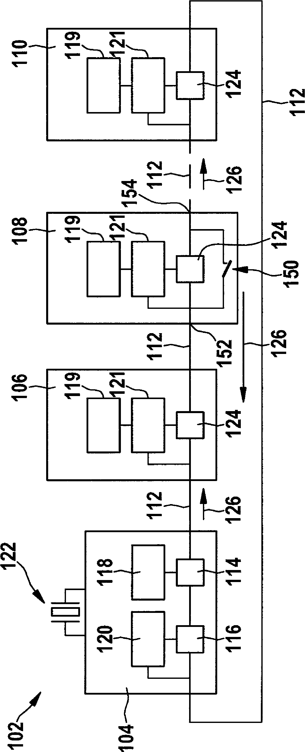
[0022] exist figure 1 The communication device 2 shown schematically in FIG. 2 is configured in a ring and comprises a plurality of subscribers connected in series one behind the other. Reference numeral 4 denotes a first user serving as the current master, reference numeral 6 denotes a second user, reference numeral 8 denotes a third user, and reference numeral 10 denotes an nth subscriber, which are connected to each other via a segment 12 of a line . Users 6, 8 and 10 act as slaves. Furthermore, the first subscriber 4 comprises a first digital serial interface 14 for sending data packets, with which the first subscriber 4 is connected, as defined, to the beginning or to the end of the line.

[0023] Furthermore, the first subscriber 4 comprises a second digital serial interface 16 for receiving data packets, ...


PUM


Abstract

The invention relates to a method for running a communication device and the communication device. In the method, bridge is assigned to at least one user, and the bridge can be used to bridging for the user.

Description

technical field [0001] The invention relates to a method for operating a communication device, in particular a ring, in which communication between users takes place. The invention also relates to such a communication device with different users having different data rates. Background technique [0002] In the field of motor vehicle technology, serial interfaces such as SPI (Serial Peripheral Interface) are used to transmit data between logic components in control devices, wherein the logic components can be designed as integrated Circuit (IC, Integrated Circuit). [0003] This standard describes bidirectional, synchronous and serial data transmission between a user configured as a master and different users configured as slaves. In this case, the interface comprises at least three lines between the master and a slave, generally two data lines and one clock line. In the case of multiple slaves, each of these users requires an additional pick or select line from the master...

Claims


Application Information

Patent Timeline
Patent Type & Authority Applications(China)
IPC IPC(8): H04L12/42
CPCH04L12/423H04L12/40013H04L12/4625
Inventor J.席尔默A-J.罗哈切克A.奥厄D.托斯U.舒尔茨T.胡克F.施密特D.厄尔特尔A.默克E.贝克S.托多罗夫
Owner ROBERT BOSCH GMBH
Learn More