Device for removing burr from inner pin hole of gear shifting oscillating bar
A shift lever and deburring technology, which is applied to metal processing equipment, large fixed members, clamping, etc., can solve problems such as low efficiency, affecting the installation of shift shafts, and poor product consistency, achieving high automation and easy operation The effect of convenience, increased production efficiency and product consistency
- Summary
- Abstract
- Description
- Claims
- Application Information
AI Technical Summary
Problems solved by technology
Method used
Image

Examples
Embodiment Construction
[0017] Below by embodiment and in conjunction with accompanying drawing, the present invention will be further described:
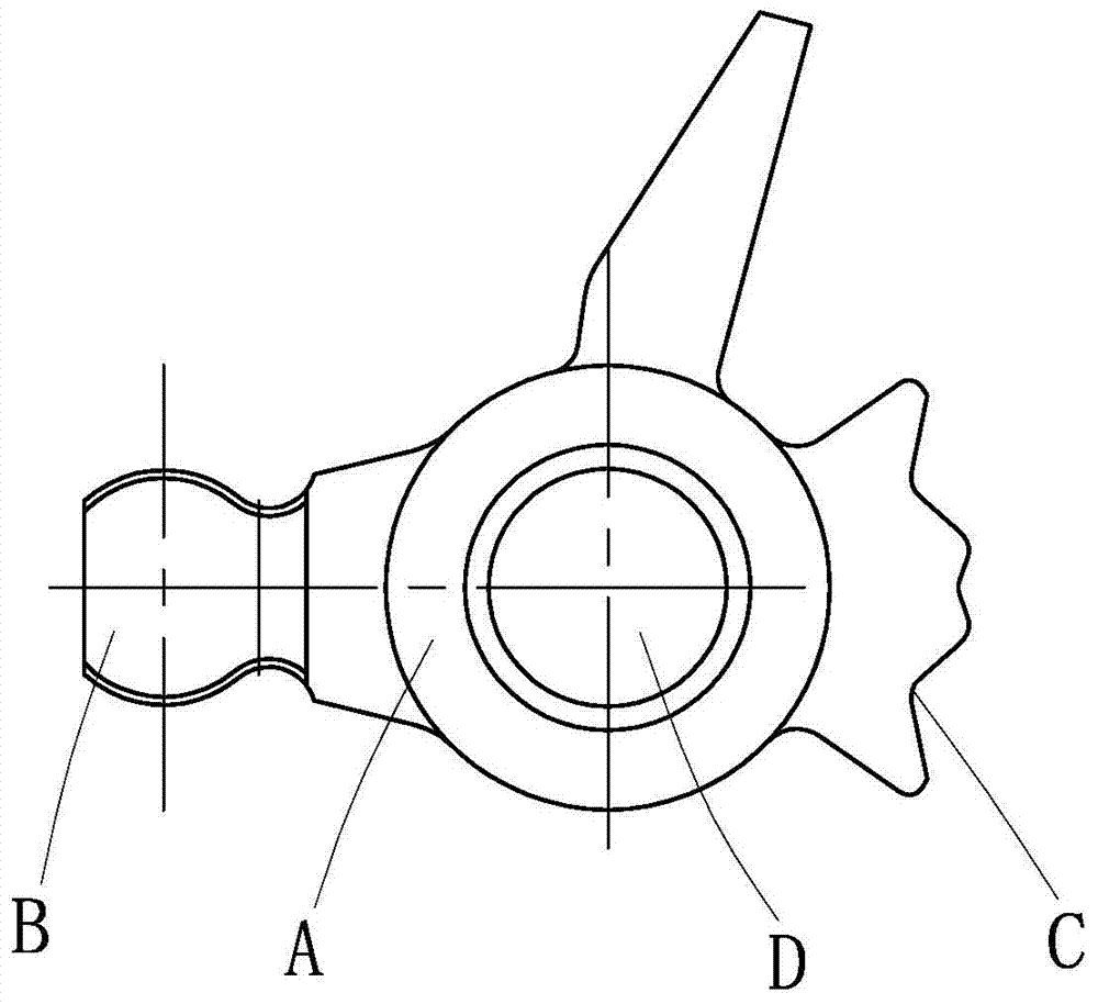
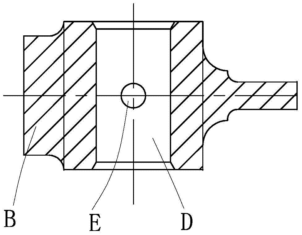
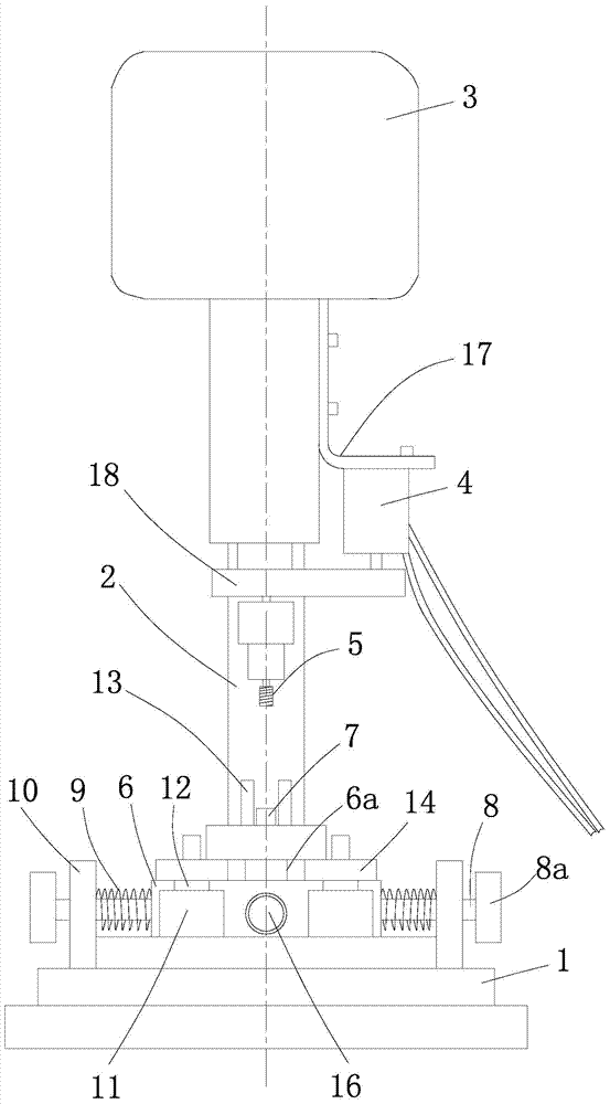
[0018] combine image 3 , Figure 4 As shown in the figure, a device for deburring the inner pin hole of the shift swing rod consists of a base 1, a support column 2, a drive motor 3, a drive cylinder 4 for the advance and retreat knife, a carbide rotary file 5, a sliding support plate 6, and an automobile swing rod sleeve column 7. Two connecting rods 8, two return springs 9, two support blocks 10, four bearings 11, four installation shafts 12, two anti-rotation blocks for car swing rods 13, two limit plates 14, several Outer hexagon bolt 15, manual fork 16, mounting bracket 17, hoop plate 18, plastic tube 19 etc. form. Except advancing and retreating knife drive cylinder 4, mounting bracket 17 and hoop plate 18, deburring equipment is left-right symmetrical structure.
[0019] The support column 2 is installed on the base 1, and the top of the suppor...
PUM
 Abstract
Description
Claims
Application Information
PatSnap Eureka turns technology decisions into work you can execute. Powered by our Innovation Knowledge Graph, it runs expert workflows across engineering, life sciences, materials and intellectual property. Get your review-ready output in minutes.


