Bearing with rolling-isolation type retainer

A cage and bearing technology, applied in the field of mechanical parts, can solve the problems of low limit speed, short service life, high heat generation, etc., and achieve the effect of high limit speed, small sliding friction resistance and excellent service life

Inactive Publication Date: 2015-01-07
闫家驹 +1
View PDF6 Cites 4 Cited by
  • Summary
  • Abstract
  • Description
  • Claims
  • Application Information

AI Technical Summary

Problems solved by technology

The main disadvantages caused by it require lubrication, high heat generation, low limit speed, short service life, etc.
[0003] At present, most of the bearings used in the market are sliding isolation cage bearings with relatively large sliding friction damage (and so called), mainly because the friction loss cannot be avoided through a reasonable structure between the cage and the rolling elements.

Method used


Image

  • Bearing with rolling-isolation type retainer
  • Bearing with rolling-isolation type retainer
  • Bearing with rolling-isolation type retainer

Examples


Embodiment

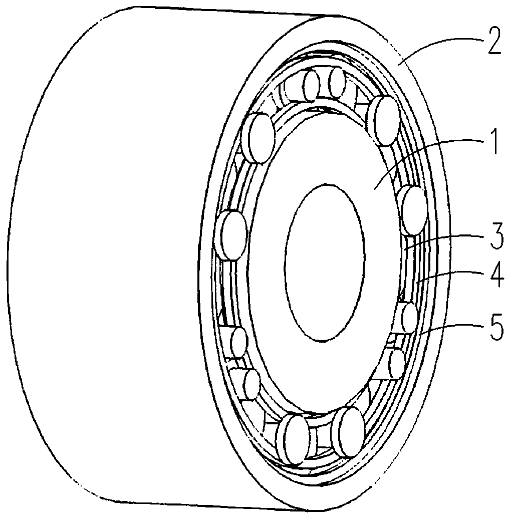
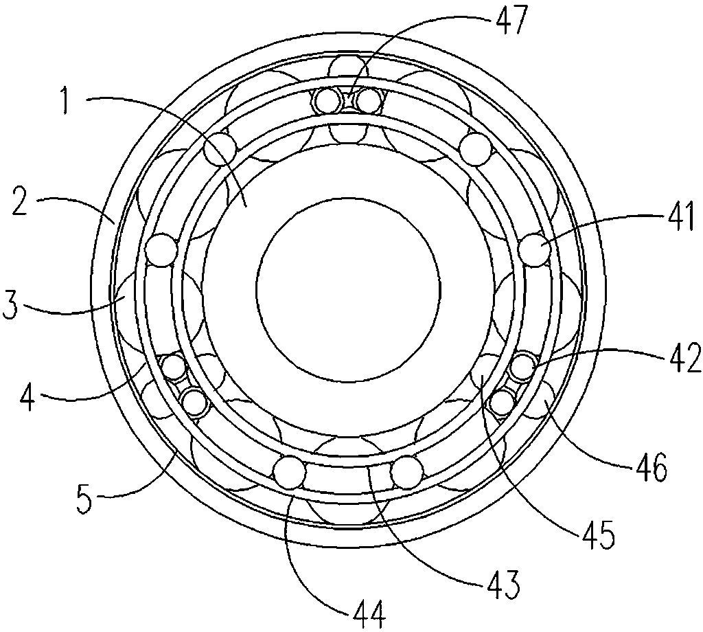
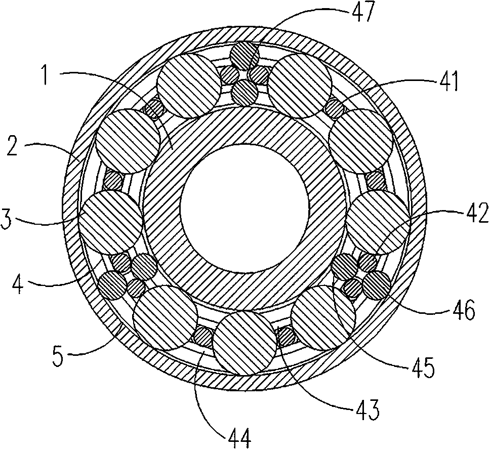
[0031] as attached Figure 1-8 As shown, a rolling isolation cage bearing with a preferred structure, the rolling element 3, the inner support roller 45 and the outer support roller 46 are cylindrical roller structures, the number of rolling elements 3 is 9, and the number of double-block isolation rollers 41 6, the number of supporting roller groups 47 is 3 groups, of which the number of single-block isolation rollers 42 is 6, and the number of supporting rollers is 6; the inner circle of the circlip 5 has inclined surfaces 51 on both sides, and the inclined surfaces 51 and the outer ring 2 The inner wall is at an angle of 100 degrees.


PUM


Abstract

The invention belongs to the field of mechanical parts and particularly relates to a bearing with a rolling-isolation type retainer. The bearing comprises an inner ring, an outer ring, rolling bodies, the retainer and clamp springs, wherein the retainer comprises double-shift isolation rollers, single-shift isolation rollers, an inner auxiliary ring, an outer auxiliary ring, inner supporting rollers and outer supporting rollers; the double-shift isolation rollers and supporting rollers groups on the rolling bodies and the retainer are uniformly arrayed and distributed between the inner ring and the outer ring at intervals; the inner sides of the rolling bodies are mounted by virtue of a roller path between baffling sides of the inner ring, and the outer sides of the rolling bodies are mounted by virtue of a roller path between the clamp springs on the side edge of the inner wall of the inner ring; the inner sides of the inner supporting rollers are mounted by virtue of the roller path between the baffling sides of the inner ring, and the outer sides of the inner supporting rollers cling to the single-shift isolation rollers; the inner sides of the outer supporting rollers cling to the single-shift isolation rollers, and the outer sides of the outer supporting rollers are mounted by virtue of a roller path between the clamp springs on the side edge of the inner wall of the outer ring. The bearing with the rolling-isolation type retainer has the beneficial effects that the frictional resistance between the retainer and each rolling body is low, the bearing can work under a non-lubrication condition, the limit speed is high, and the service life of the bearing is far longer than that of an existing bearing in the equal work environment conditions.

Description

technical field [0001] The invention belongs to the field of mechanical parts, in particular to a rolling isolation cage bearing with a novel structure. Background technique [0002] Bearings are mechanical parts commonly used in mechanical equipment. Rolling bearings generally consist of inner rings, outer rings, rolling elements and cages. The main wear and consumption of bearings in high-speed operation is caused by friction, which mainly includes rolling friction and sliding friction. The main parts where sliding friction occurs are: the contact surface between the rolling element and the raceway, the contact surface between the rolling element and the pocket of the cage, between the cage and the guide rib of the ferrule, and between the end surface of the roller and the guide of the ferrule. Wait between the sides. The sliding friction resistance generated between the sliding isolation cage and the rollers will bring a series of disadvantages to the bearing, and it m...

Claims


Application Information

Patent Timeline
Patent Type & Authority Applications(China)
IPC IPC(8): F16C33/30
Inventor 闫家驹黄存杰
Owner 闫家驹
Why Eureka
Try Eureka