

Self-lubricating gear
A self-lubricating, gear technology, applied in belts/chains/gears, components with teeth, portable lifting devices, etc., can solve problems such as shortened service life, wear, and single function of gears, so as to avoid wear and prolong service life Effect
Inactive Publication Date: 2015-01-07
CHANGZHOU FUYUN CHEM
View PDF4 Cites 11 Cited by
- Summary
- Abstract
- Description
- Claims
- Application Information
AI Technical Summary
Problems solved by technology
The existing gear functions are relatively simple, without self-lubricating function, the wear is serious after long-term work, and the service life is obviously shortened
Method used
View moreImage
Smart ImageViewing Examples

Examples
Embodiment Construction
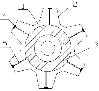
[0009] Such as figure 1 It is a structural schematic diagram of the present invention, a self-lubricating gear, including a gear body 1 and gear teeth 2 installed on the periphery of the gear body 1, the gear body 1 is provided with an oil storage ring 3, and the end of the gear teeth 2 is provided with an outlet The oil hole 4, the oil outlet hole 4 and the oil storage ring 3 are connected through the oil guide pipe 5. During the transmission process, the oil in the oil storage ring 3 flows out from the oil outlet hole 4 through the oil guide pipe 5 to play the role of lubrication.
[0010] The improved self-lubricating gear realizes automatic lubrication to avoid wear and prolong the service life of the gear.
Login to View More PUM
 Abstract
The invention relates to the technical field of mechanical transmission, in particular to a self-lubricating gear. Functions of an existing gear are single, the existing gear does not have a self-lubricating function and is seriously abraded after working for a long time, and the service life of the existing gear is obviously shortened. The self-lubricating gear comprises a gear body and gear teeth mounted on the periphery of the gear body, an oil storage ring is arranged in the gear body, and oil outlet holes are formed in the ends of the gear teeth and connected with the oil storage ring through an oil lead pipe. The improved self-lubricating gear automatically lubricates, abrasion is avoided, and the service life of the gear is prolonged.
Description
technical field [0001] The invention relates to the technical field of mechanical transmission, in particular to a self-lubricating gear. Background technique [0002] A gear is a mechanical element that has teeth on the rim and can continuously mesh to transmit motion and power. It is a toothed mechanical part that can mesh with each other. The application of gears in transmission has appeared very early. The existing gears have single functions and no self-lubricating function. After working for a long time, the wear is serious and the service life is obviously shortened. Contents of the invention [0003] In order to overcome the existing severe wear problem, the invention provides a self-lubricating gear. [0004] The technical solution adopted by the present invention to solve the technical problem is: a self-lubricating gear, including a gear body and gear teeth installed on the periphery of the gear body, an oil storage ring is arranged inside the gear body, and an...
Claims
Login to View More Application Information
Patent Timeline
 IPC IPC(8): F16H55/17
CPCF16H55/17
Inventor 徐少伟
Owner CHANGZHOU FUYUN CHEM