Electric initiating explosive device component with high safety and low energy consumption

It is a technology of electric explosive products and low energy consumption, which is applied in the direction of weapon accessories, blasting barrels, offensive equipment, etc. It can solve the problems of high ignition energy, reduce the diameter of bridge wire, reduce the safety current, etc., and achieve the effect of simple working conditions

Active Publication Date: 2015-01-07
北京博创精芯科技有限公司
View PDF10 Cites 3 Cited by
  • Summary
  • Abstract
  • Description
  • Claims
  • Application Information

AI Technical Summary

Problems solved by technology

There are obvious defects in metal bridge wires in actual design and application: first, when higher safety current (≥100mA) is required, higher ignition voltage (≥28V) and higher ignition energy (≥10mJ); In order to reduce the ignition voltage, ignition current and ignition energy of the metal bridge wire, the diameter of the bridge wire must be reduced to increase the sensitivity of the ignition powder, resulting in a decrease in the safety current of the EED, and also reducing the antistatic resistance of the EED. The ability of electromagnetic interference, which means that in order to make the low-energy and reliable ignition of EEDs, the safety of EEDs needs to be reduced
[0003] Traditional EEDs have the following problems: If EEDs have a higher safety current, they also have higher ignition energy and ignition voltage; and if the ignition energy and ignition voltage of EEDs are reduced, EEDs will The safety current of the product will be reduced, resulting in a reduction in the safety of the finished electrical pyrotechnic product

Method used


Image

  • Electric initiating explosive device component with high safety and low energy consumption
  • Electric initiating explosive device component with high safety and low energy consumption
  • Electric initiating explosive device component with high safety and low energy consumption

Examples


Embodiment 1

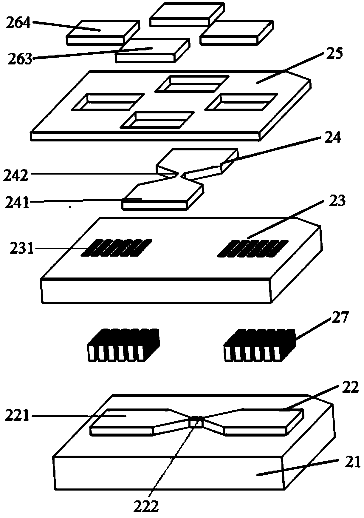
[0030] Such as figure 1 As shown, the electronic switch of the high-safety and low-energy-consumption electric explosive component includes: an electronic switch substrate 21, a control bridge 22, an insulating layer 23, a wire bridge 24, a passivation layer 25, a metal interconnection 27, and a pair of control bridge electrodes Pads 264 and a pair of wire bridge electrode pads 263; wherein, the control bridge 22 is formed on the substrate 21, including a pair of control bridge electrodes 221, and a control bridge bridge region 222 connecting the two; the insulating layer 23 covers the control bridge On the bridge 22; on the insulating layer 23, a plurality of through holes 231 are arranged at the position facing the pair of control bridge electrodes 221 of the control bridge 22, forming a through hole array; the wire bridge 24 is formed on the insulating layer 23, including a pair of wires Bridge electrode 241, and the wire bridge bridge area 242 that connects the two; The c...

Embodiment 2

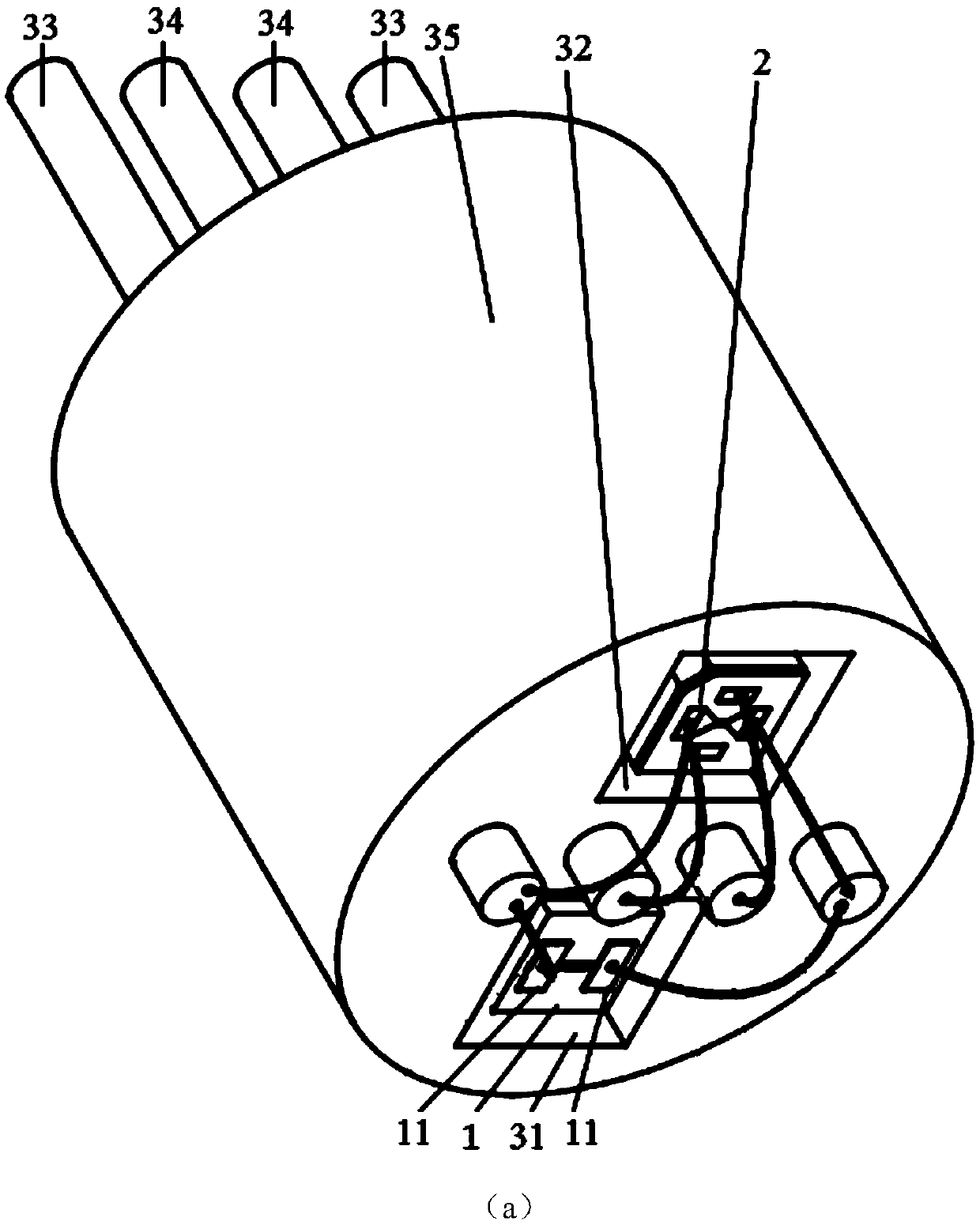
[0034] In this embodiment, the electronic switch 2 is packaged in the packaging structure 28, and the packaging structure includes a through hole, a pair of packaging structure control pads 284 and a pair of packaging structure wire pads 283; the upper surface of the packaging structure 28 is provided with a through hole , the through hole is facing the area where the electric explosion occurs in the electronic switch, and a pair of packaging structure control pads 284 and a pair of packaging structure wire pads 283 are exposed on the lower surface of the packaging structure 28, and a pair of control bridge electrodes of the electronic switch are soldered The pads 264 are respectively connected to a pair of packaging structure control pads 284 by wire bonding; the pair of wire bridge electrode pads 263 of the electronic switch are respectively connected to a pair of packaging structure wire pads 283 by wire bonding. The package structure 28 with the electronic switch 2 packaged...

Embodiment 3

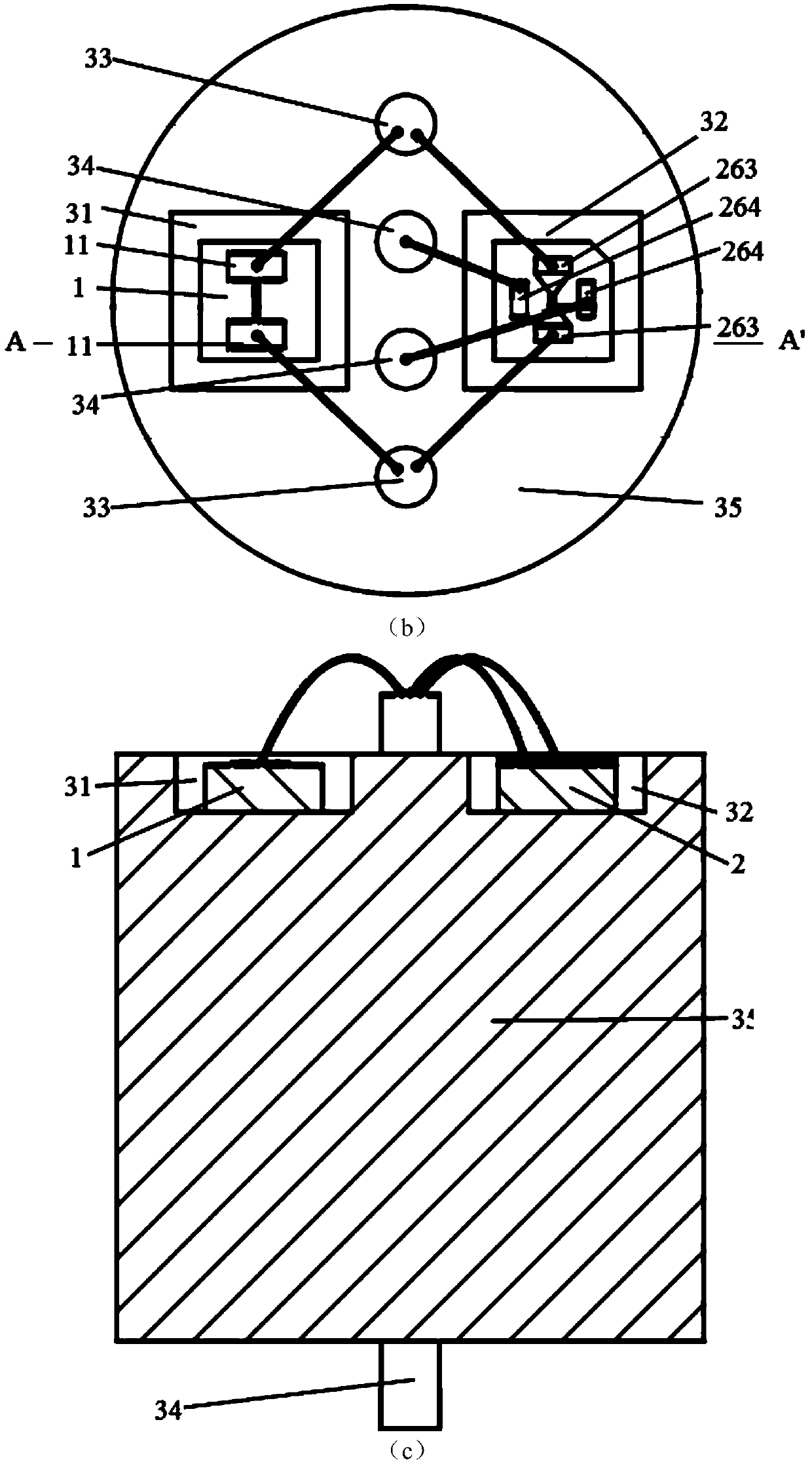
[0036] In this embodiment, the package body adopts the substrate 4, and the substrate adopts a printed circuit board PCB substrate, or a ceramic substrate. Parallel connection of switches and electrical explosives. Such as Figure 4 As shown, the substrate includes a base, a pair of ignition circuit pads and a pair of safety circuit pads; wherein, the two ignition electrodes 11 of the electrical pyrotechnic device 1 are respectively connected to a pair of ignition circuit pads 43 of the substrate; the electronic switch A pair of wire bridge electrode pads 263 of 2 are respectively connected to a pair of ignition circuit pads 43 of the substrate to realize the parallel connection of electronic switch 2 and electrical pyrotechnic device 1, and a pair of ignition circuit pads 43 are respectively connected through metal wiring 46. To the external ignition control circuit of electrical pyrotechnics; a pair of control bridge electrode pads 264 of the electronic switch 2 are respect...


PUM


Abstract

The invention discloses an electric initiating explosive device component with high safety and low energy consumption. The electric initiating explosive device component comprises an electric initiating explosive device, an electronic switch and a packaging body; the electronic switch and the packaging body are arranged in the packaging body; the electronic switch is connected with the electric initiating explosive device in parallel; in the non-ignition state, the electronic switch is in the normal open state, and at the moment, the electric initiating explosive device is in a short circuit state and has the high safety current and high safety; in the ignition state, the electronic switch is disconnected, the electric initiating explosive device has access to an ignition control circuit, normal ignition can be achieved only through the low ignition energy and ignition voltage, and the low-energy ignition capability is achieved. The electric initiating explosive device component has the high safety and the low-energy ignition capability at the same time, and meanwhile due to the simple working condition of the electronic switch, a complex peripheral circuit is not needed.

Description

technical field [0001] The invention relates to the technology of electrical explosive devices, in particular to an electrical explosive device assembly with low ignition energy and high safety current. Background technique [0002] Traditional EED components mainly include metal bridge wires, explosive foils, reactive bridges, semiconductor bridges and metal film bridges. Wherein, the metal bridge wire is welded between two metal electrodes, and when the metal electrodes are fed with electric current, the bridge wire heats up and ignites the propellant in contact with the bridge wire. There are obvious defects in metal bridge wires in actual design and application: first, when higher safety current (≥100mA) is required, higher ignition voltage (≥28V) and higher ignition energy (≥10mJ); In order to reduce the ignition voltage, ignition current and ignition energy of the metal bridge wire, the diameter of the bridge wire must be reduced to increase the sensitivity of the ign...

Claims


Application Information

Patent Timeline
Patent Type & Authority Applications(China)
IPC IPC(8): F42B3/12
Inventor 娄文忠丁旭冉赵越
Owner 北京博创精芯科技有限公司
Why Eureka
Try Eureka